Dell Force10 S55T Installing the S55 System - Page 19
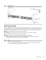
Attach ground cable, shipping to properly ground the chassis. The one-hole lug must be a UL recognized
 |
View all Dell Force10 S55T manuals
Add to My Manuals
Save this manual to your list of manuals |
Page 19 highlights
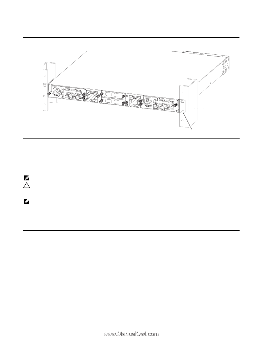
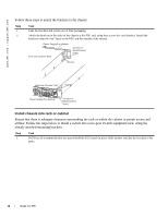
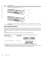
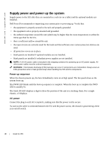
Step Task (continued) 2 Attach the bracket "ears" to the rack or cabinet posts, using two screws for each bracket. Ensure the screws are tightened firmly. PSU0 PSU1 Rack/Cabinet Post Rack Mounting ears Attach ground cable The S55 is shipped with 1 10-32 screws for attaching a ground cable to the chassis. The cable itself is not included. Dell Force10 recommends a 6AWG one-hole lug, #10 hole size, 63" spacing (not included in shipping) to properly ground the chassis. The one-hole lug must be a UL recognized, crimp-type lug. NOTE: The rack installation ears are not suitable for grounding. CAUTION: Grounding conductors must be made of copper. Do not use aluminum conductors. Follow these steps to connect the ground cable to the chassis. NOTE: Coat the one-hole lug with an anti-oxidant compound prior to crimping. Bring any un-plated mating surfaces to a shiny finish, and coat with an anti-oxidant prior to mating. Plated mating surfaces must be clean and free from contamination. Step Task 1 Take the (1) 10-32 screw from the package. 2 Cut cable to desired length. Cable length must facilitate the proper operation of fault interrupt circuits. Dell Force10 recommends using of the shortest cable route allowable. Install the S55 | 19
-
 1
1 -
2
-
3
-
4
-
5
-
6
-
7
-
8
-
9
-
10
-
11
-
12
-
13
-
 14
14 -
 15
15 -
 16
16 -
 17
17 -
 18
18 -
 19
19 -
 20
20 -
 21
21 -
 22
22 -
 23
23 -
 24
24 -
25
-
26
-
27
-
28
-
29
-
30
-
31
-
32
-
33
-
34
-
35
-
36
-
37
-
38
-
39
-
40
-
41
-
42
-
43
-
44
-
45
-
46
-
47
-
48
-
49
-
50
 |
 |