Dell Force10 S55T Installing the S55 System - Page 7
The S55 System, Introduction - s55 stacking module
 |
View all Dell Force10 S55T manuals
Add to My Manuals
Save this manual to your list of manuals |
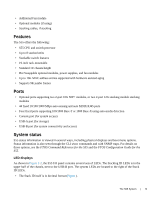
Page 7 highlights
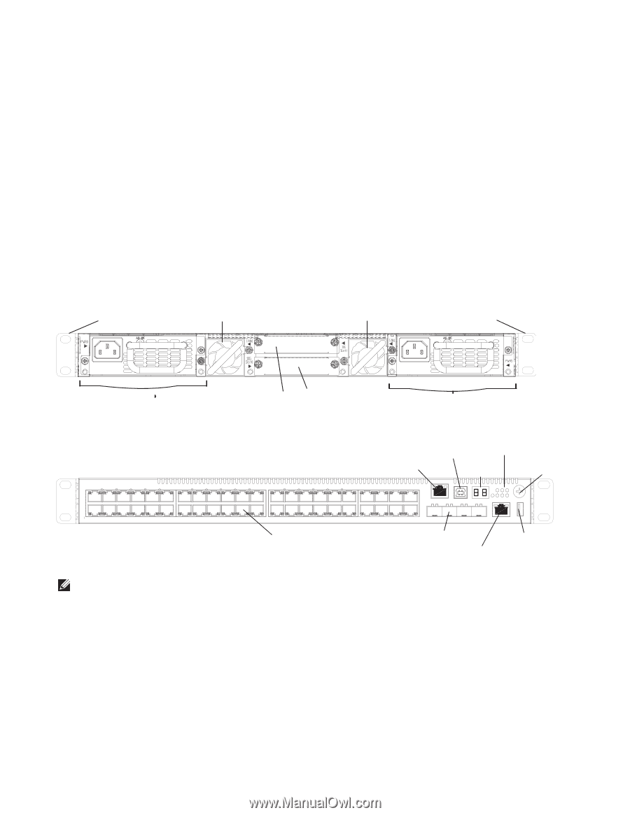
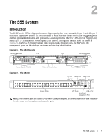
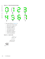
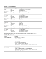
2 The S55 System Introduction The Dell Force10 S55 is a high performance, high capacity, low cost, stackable, Layer 2 switch/Layer 3 router that supports 44 built-in 10/100/1000 Base-T ports, four SFP (small form-factor pluggable) ports, and two optional module slots, and optional 12G stacking module. The S55's PSU (Power Supply Unit) side (Figure 2-1) contains the Power Supply Units (PSUs), and optional module slots. As shown in Figure 2-2, the S55's I/O (Input/Output) side contains the 44 Ethernet ports, the SFP ports, the management ports and the displays for alarms and stacking identification. Figure 2-1. The S55 PSU side Mounting Bracket Fan Fan Mounting Bracket Power Supply (PSU0) Figure 2-2. The S55 I/O Optional Module slots Power Supply (PSU1) RJ-45 USB-B Port Alarm LEDs Console Port Stack ID Grounding Ethernet Ports SFP Ports USB-A Port 10/100/1000 Management Port NOTE: The Ethernet ports are labeled 0-43. When cabling these ports, be sure not to interfere with the airflow from the small vent holes above and below the ports. The S55 System | 7
-
 1
1 -
 2
2 -
 3
3 -
 4
4 -
 5
5 -
 6
6 -
 7
7 -
 8
8 -
 9
9 -
 10
10 -
 11
11 -
 12
12 -
13
-
14
-
15
-
16
-
17
-
18
-
19
-
20
-
21
-
22
-
23
-
24
-
25
-
26
-
27
-
28
-
29
-
30
-
31
-
32
-
33
-
34
-
35
-
36
-
37
-
38
-
39
-
40
-
41
-
42
-
43
-
44
-
45
-
46
-
47
-
48
-
49
-
50
 |
 |