Dell Force10 S55T Installing the S55 System - Page 22
Connect two S55s, transfer between the units. - s55 stacking
 |
View all Dell Force10 S55T manuals
Add to My Manuals
Save this manual to your list of manuals |
Page 22 highlights
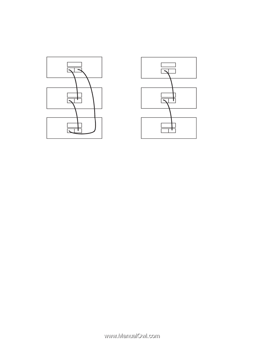
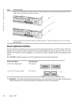
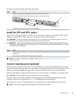
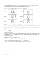
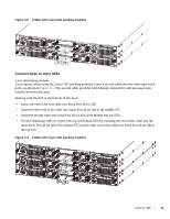
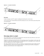
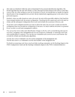
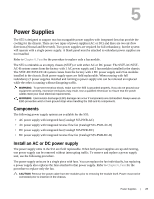
www.dell.com | support.dell.com The S55 supports stacking in either a ring or cascade topology. Dell Force10 recommends the ring topology when stacking S55 switches, to provide redundant connectivity. Figure 4-1. S55 stacking topology with 2-port 12G stacking module Switch 1 48 49 Switch 1 48 49 Switch 2 48 49 Switch 2 48 49 Switch 3 48 49 Switch 3 48 49 While the diagram shows A-to-B connections, the ports are bi-directional, so you can connect A-to-A or B-to-B, as shown below in examples of two-switch (Figure 4-2 or Figure 4-3). Rack-mount the switches or insert them into a cabinet before you make your stacking port connections. Insert one end of the stacking cable into a stacking port, and insert the other end into a stacking port of the adjacent switch. Hand-tighten all captive screws to ensure that the cable is secure in the connector. Connect two S55s 2-port 12G stacking modules As an option, when using the 2-port 12G stacking modules, insert a second cable into the other open stack ports, as shown in Figure 4-2. The second cable provides both backup connectivity and increased data transfer between the units. Starting with the S55 at the bottom of the stack: • Insert one end of the first cable into Stack Port 48 (or 49). • Insert the other end of the cable into Stack Port 48 (or 49) of the top. • Insert a second cable into Stack Port 49 (or 48) of the bottom and top S55s. 22 | Install the S55
-
 1
1 -
2
-
3
-
4
-
5
-
6
-
7
-
8
-
9
-
10
-
11
-
12
-
13
-
14
-
15
-
16
-
 17
17 -
 18
18 -
 19
19 -
 20
20 -
 21
21 -
 22
22 -
 23
23 -
 24
24 -
 25
25 -
 26
26 -
 27
27 -
28
-
29
-
30
-
31
-
32
-
33
-
34
-
35
-
36
-
37
-
38
-
39
-
40
-
41
-
42
-
43
-
44
-
45
-
46
-
47
-
48
-
49
-
50
 |
 |