Dell Force10 S55T Installing the S55 System - Page 9
Features, Ports, System status, LED displays
 |
View all Dell Force10 S55T manuals
Add to My Manuals
Save this manual to your list of manuals |
Page 9 highlights
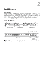
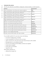
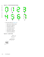
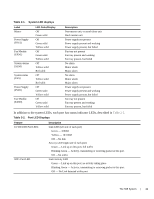
• Additional Fan module • Optional modules (if using) • Stacking cables, if stacking Features The S55 offers the following: • S55 CPU and switch processor • Up to 8 stacked units • Stackable switch features • 19-inch rack-mountable • Standard 1U chassis height • Hot Swappable optional modules, power supplies, and fan modules • Up to 16K MAC address entries supported with hardware assisted aging • Supports 9K jumbo frames Ports • Optional ports supporting two 2-port 10G SFP+ modules, or two 2-port 12G stacking module stacking modules • 44 fixed 10/100/1000 Mbps auto-sensing and auto MDIX RJ45 ports • Four fixed ports supporting 100/1000 Base-T or 1000 Base-X using auto-media detection • Console port (for system access) • USB-A port (for storage) • USB-B port (for system connectivity and access) System status S55 status information is viewed in several ways, including physical displays and boot menu options. Status information is also seen through the CLI show commands and with SNMP traps. For details on those options, see the FTOS Command Reference for the S55 and the FTOS Configuration Guide for the S55. LED displays As shown in Figure 2-2, the S55 I/O panel contains several sets of LEDs. The Stacking ID LEDs is in the upper half of the chassis, next to the USB-B port. The system LEDs are located to the right of the Stack ID LEDs. • The Stack ID itself is in decimal format (Figure ). The S55 System | 9
-
 1
1 -
2
-
3
-
 4
4 -
 5
5 -
 6
6 -
 7
7 -
 8
8 -
 9
9 -
 10
10 -
 11
11 -
 12
12 -
 13
13 -
 14
14 -
15
-
16
-
17
-
18
-
19
-
20
-
21
-
22
-
23
-
24
-
25
-
26
-
27
-
28
-
29
-
30
-
31
-
32
-
33
-
34
-
35
-
36
-
37
-
38
-
39
-
40
-
41
-
42
-
43
-
44
-
45
-
46
-
47
-
48
-
49
-
50
 |
 |