Dell Inspiron 16 7610 Service Manual for computers with two fans - Page 46
Installing the power-button board
 |
View all Dell Inspiron 16 7610 manuals
Add to My Manuals
Save this manual to your list of manuals |
Page 46 highlights
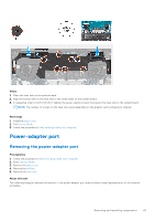
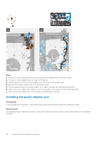
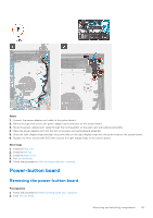
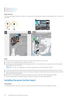
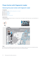
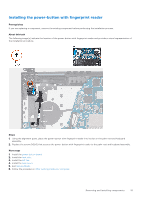
3. Remove the base cover. 4. Remove the heat sink. 5. Remove the left fan. About this task The following image(s) indicate the location of the power-button board and provides a visual representation of the removal procedure. Steps 1. Remove the three screws (M2.5x5) that secure the left-display hinge to the I/O board. 2. Pry open the left-display hinge at an angle of 90 degrees. 3. Lift the power-button with fingerprint-reader cable-connector latch and disconnect the power-button with fingerprint- reader cable from the I/O board. NOTE: This step is only applicable for computers shipped with the optional fingerprint reader. 4. Lift the power-button board cable-connector latch and disconnect the power-button board cable from the I/O board. 5. Peel the tape that secures the power-button with optional fingerprint reader cable and power-button board cable to the palm-rest and keyboard assembly. 6. Remove the screw (M2x3) that secures the power-button board to the palm-rest and keyboard assembly. 7. Lift the power-button with optional fingerprint reader off the palm-rest and keyboard assembly. Installing the power-button board Prerequisites If you are replacing a component, remove the existing component before performing the installation process. 46 Removing and installing components
-
 1
1 -
2
-
3
-
4
-
5
-
6
-
7
-
8
-
9
-
10
-
11
-
12
-
13
-
14
-
15
-
16
-
17
-
18
-
19
-
20
-
21
-
22
-
23
-
24
-
25
-
26
-
27
-
28
-
29
-
30
-
31
-
32
-
33
-
34
-
35
-
36
-
37
-
38
-
39
-
40
-
 41
41 -
 42
42 -
 43
43 -
 44
44 -
 45
45 -
 46
46 -
 47
47 -
 48
48 -
 49
49 -
 50
50 -
 51
51 -
52
-
53
-
54
-
55
-
56
-
57
-
58
-
59
-
60
-
61
-
62
-
63
-
64
-
65
-
66
-
67
-
68
-
69
-
70
-
71
-
72
-
73
-
74
-
75
-
76
-
77
 |
 |
