Dell Inspiron 16 7610 Service Manual for computers with two fans - Page 52
System board, Removing the system board
 |
View all Dell Inspiron 16 7610 manuals
Add to My Manuals
Save this manual to your list of manuals |
Page 52 highlights
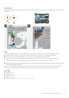
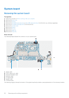
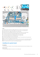
System board Removing the system board Prerequisites 1. Follow the procedure in Before working inside your computer. 2. Remove the base cover. 3. Remove the memory. 4. Remove the M.2 2230 solid-state drive or M.2 2280 solid-state drive from M.2 slot one, whichever applicable 5. Remove the M.2 2230 solid-state drive from M.2 slot two. 6. Remove the wireless card. 7. Remove the battery. 8. Remove the left fan. 9. Remove the right fan. 10. Remove the heat sink. About this task The following image indicates the connectors on your system board. 1. Display cable 2. Power-adapter port cable 3. Keyboard-backlight cable 4. Keyboard cable 5. Touchpad cable 6. Speaker cable 7. I/O-board cable The following image(s) indicate the location of the system board and provides a visual representation of the removal procedure. 52 Removing and installing components
-
 1
1 -
2
-
3
-
4
-
5
-
6
-
7
-
8
-
9
-
10
-
11
-
12
-
13
-
14
-
15
-
16
-
17
-
18
-
19
-
20
-
21
-
22
-
23
-
24
-
25
-
26
-
27
-
28
-
29
-
30
-
31
-
32
-
33
-
34
-
35
-
36
-
37
-
38
-
39
-
40
-
41
-
42
-
43
-
44
-
45
-
46
-
 47
47 -
 48
48 -
 49
49 -
 50
50 -
 51
51 -
 52
52 -
 53
53 -
 54
54 -
 55
55 -
 56
56 -
 57
57 -
58
-
59
-
60
-
61
-
62
-
63
-
64
-
65
-
66
-
67
-
68
-
69
-
70
-
71
-
72
-
73
-
74
-
75
-
76
-
77
 |
 |
