Dell Inspiron 16 7635 2-in-1 Owners Manual - Page 72
System board, Removing the system board
 |
View all Dell Inspiron 16 7635 2-in-1 manuals
Add to My Manuals
Save this manual to your list of manuals |
Page 72 highlights
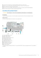
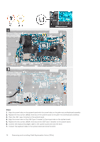
Steps 1. Place the palm-rest and keyboard assembly on a clean and flat surface. 2. Place the display assembly on the palm-rest and keyboard assembly. CAUTION: To avoid damaging the display, do not slide the display assembly. 3. Align the screw holes on the left display hinge with the screw holes on the palm-rest and keyboard assembly. 4. Replace the two screws (M2.5x5) and the screw (M2x4) that secure the left display hinge to the palm-rest and keyboard assembly. 5. Align the screw holes on the right display hinge with the screw holes on the system board. 6. Replace the two screws (M2.5x5) and the screw (M2x4) that secure the right display hinge to the palm-rest and keyboard assembly. 7. Close the display lid and place the computer on a clean and flat surface. 8. Connect the touch-screen cable to the connector on the system board and close the latch. 9. Connect the display cable to the connector on the system board and close the latch. 10. Adhere the tape that secures the display-cable connector latch to the system board. 11. Route the display-speaker cable through the routing guides on the palm-rest and keyboard assembly. 12. Connect the display-speaker cable to the speaker board. Next steps 1. Install the base cover. 2. Follow the procedure in After working inside your computer. System board Removing the system board CAUTION: The information in this section is intended for authorized service technicians only. 72 Removing and installing Field Replaceable Units (FRUs)
-
 1
1 -
2
-
3
-
4
-
5
-
6
-
7
-
8
-
9
-
10
-
11
-
12
-
13
-
14
-
15
-
16
-
17
-
18
-
19
-
20
-
21
-
22
-
23
-
24
-
25
-
26
-
27
-
28
-
29
-
30
-
31
-
32
-
33
-
34
-
35
-
36
-
37
-
38
-
39
-
40
-
41
-
42
-
43
-
44
-
45
-
46
-
47
-
48
-
49
-
50
-
51
-
52
-
53
-
54
-
55
-
56
-
57
-
58
-
59
-
60
-
61
-
62
-
63
-
64
-
65
-
66
-
 67
67 -
 68
68 -
 69
69 -
 70
70 -
 71
71 -
 72
72 -
 73
73 -
 74
74 -
 75
75 -
 76
76 -
 77
77 -
78
-
79
-
80
-
81
-
82
-
83
-
84
-
85
-
86
-
87
-
88
-
89
-
90
-
91
-
92
-
93
-
94
-
95
-
96
-
97
 |
 |
