Dell Inspiron 16 7635 2-in-1 Owners Manual - Page 77
Palm-rest and keyboard assembly
 |
View all Dell Inspiron 16 7635 2-in-1 manuals
Add to My Manuals
Save this manual to your list of manuals |
Page 77 highlights
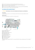
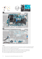
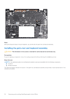
8. Connect the touchpad cable to the system board and close the latch. 9. Connect the speaker-board cable to the connector on the system board. 10. Connect the speaker cables to the connector on the system board. 11. Connect the I/O board cable to the connector on the system board and close the latch. 12. Connect the fan cable to the connector on the system board. Next steps 1. Install the heat sink. 2. Install the fan. 3. Install the display assembly. 4. Install the wireless card. 5. Install the M.2 2230 solid-state drive or the M.2 2280 solid-state drive , whichever is applicable. 6. Install the 4-cell battery (64 Wh) or the 6-cell battery (86 Wh), whichever is applicable. 7. Install the base cover. 8. Follow the procedure in After working inside your computer. Palm-rest and keyboard assembly Removing the palm-rest and keyboard assembly CAUTION: The information in this section is intended for authorized service technicians only. Prerequisites 1. Follow the procedure in Before working inside your computer. 2. Remove the base cover. 3. Remove the 4-cell battery (64 Wh) or the 6-cell battery (86 Wh), whichever is applicable. 4. Remove the M.2 2230 solid-state drive or the M.2 2280 solid-state drive, whichever is applicable. 5. Remove the wireless card. 6. Remove the fan. 7. Remove the coin-cell battery. 8. Remove the I/O board. 9. Remove the system board. NOTE: The system board can be removed with the heat sink attached. 10. Remove the power button or the power button with fingerprint reader, whichever is applicable. 11. Remove the speaker board. 12. Remove the speakers. 13. Remove the display assembly. About this task The following image(s) indicate the location of the palm-rest and keyboard assembly and provides a visual representation of the removal procedure. Removing and installing Field Replaceable Units (FRUs) 77
-
 1
1 -
2
-
3
-
4
-
5
-
6
-
7
-
8
-
9
-
10
-
11
-
12
-
13
-
14
-
15
-
16
-
17
-
18
-
19
-
20
-
21
-
22
-
23
-
24
-
25
-
26
-
27
-
28
-
29
-
30
-
31
-
32
-
33
-
34
-
35
-
36
-
37
-
38
-
39
-
40
-
41
-
42
-
43
-
44
-
45
-
46
-
47
-
48
-
49
-
50
-
51
-
52
-
53
-
54
-
55
-
56
-
57
-
58
-
59
-
60
-
61
-
62
-
63
-
64
-
65
-
66
-
67
-
68
-
69
-
70
-
71
-
 72
72 -
 73
73 -
 74
74 -
 75
75 -
 76
76 -
 77
77 -
 78
78 -
 79
79 -
 80
80 -
 81
81 -
 82
82 -
83
-
84
-
85
-
86
-
87
-
88
-
89
-
90
-
91
-
92
-
93
-
94
-
95
-
96
-
97
 |
 |
