Dell Inspiron 546s Service Manual - Page 25
Replacing the Processor Fan and Heat Sink Assembly
 |
View all Dell Inspiron 546s manuals
Add to My Manuals
Save this manual to your list of manuals |
Page 25 highlights
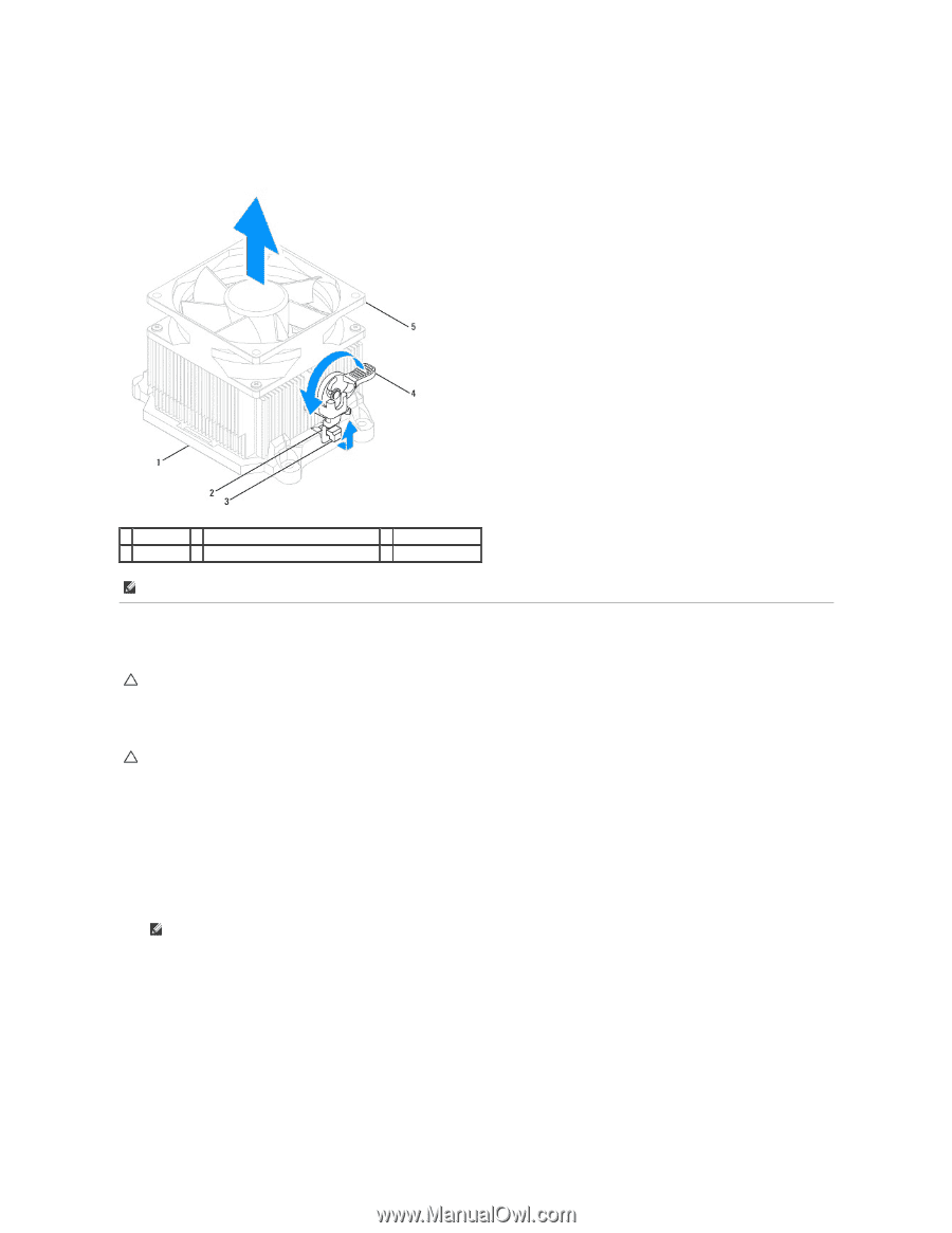
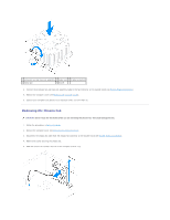
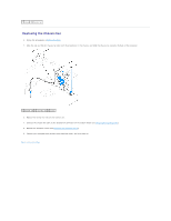
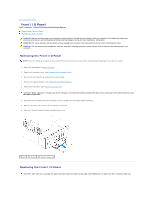
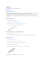
Inspiron 546s a. Rotate the clamp lever 180 degrees counter-clockwise to release the clamp grip from the bracket projection. b. Rotate the processor fan and heat sink assembly upward gently, and remove it from the computer. Lay the processor fan and heat sink assembly down on its top, with the thermal grease facing upward. 1 bracket 2 clamp grip 3 bracket projection 4 clamp lever 5 processor fan and heat sink assembly NOTE: The processor fan and heat sink assembly in your computer may not look exactly like the one shown in the illustration above. Replacing the Processor Fan and Heat Sink Assembly CAUTION: When reinstalling the fan, ensure that you do not pinch the wires that run between the system board and the fan. 1. Clean the thermal grease from the bottom of the processor fan and heat sink assembly. CAUTION: Ensure that you apply new thermal grease. New thermal grease is critical for ensuring adequate thermal bonding, which is a requirement for optimal processor operation. 2. Apply the new thermal grease to the top of the processor. 3. Replace the processor fan and heat sink assembly. Inspiron 535s/537s/545s a. Align the captive screws on the processor fan and heat sink assembly to the four metal screw hole projections on the system board. b. Tighten the four captive screws that secure the processor fan and heat sink assembly to the system board. NOTE: Ensure that the processor fan and heat sink assembly is correctly seated and secure. Inspiron 546s a. Place the processor fan and heat sink assembly back onto the bracket. b. Ensure that the two clamp grips are aligned with the two bracket projections. c. Hold the processor fan and heat sink fan assembly in place and rotate the clamp lever 180 degrees clockwise to secure the processor fan and heat sink assembly.
-
 1
1 -
2
-
3
-
4
-
5
-
6
-
7
-
8
-
9
-
10
-
11
-
12
-
13
-
14
-
15
-
16
-
17
-
18
-
19
-
 20
20 -
 21
21 -
 22
22 -
 23
23 -
 24
24 -
 25
25 -
 26
26 -
 27
27 -
 28
28 -
 29
29 -
 30
30 -
31
-
32
-
33
-
34
-
35
-
36
-
37
-
38
-
39
-
40
-
41
-
42
-
43
-
44
-
45
-
46
-
47
-
48
-
49
 |
 |