Dell Inspiron E1705 Owner's Manual - Page 128
Connect the antenna cables to the antenna connectors on the Mini-Card by matching the color
 |
View all Dell Inspiron E1705 manuals
Add to My Manuals
Save this manual to your list of manuals |
Page 128 highlights
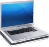
NOTICE: The connectors are keyed to ensure correct insertion. If you feel resistance, check the connectors and realign the card. 5 Install the replacement Mini-Card: a Align the Mini-Card with the connector at a 45-degree angle, and press the Mini-Card down into the securing clips until the card clicks into place. 3 2 1 1 securing clips 2 antenna connectors (2) 3 Mini-Card connector NOTICE: To avoid damaging the Mini-Card, never place cables under the card. b Connect the antenna cables to the antenna connectors on the Mini-Card by matching the color of the cable to the color of the triangle above the connector. Connect the main antenna cable (white) to the antenna connector with the white triangle. Connect the auxiliary antenna cable (black) to the antenna connector with the black triangle. NOTE: If your computer has a gray cable, connect it to the connector with the gray triangle, if one is available on your card. 128 Adding and Replacing Parts
-
 1
1 -
2
-
3
-
4
-
5
-
6
-
7
-
8
-
9
-
10
-
11
-
12
-
13
-
14
-
15
-
16
-
17
-
18
-
19
-
20
-
21
-
22
-
23
-
24
-
25
-
26
-
27
-
28
-
29
-
30
-
31
-
32
-
33
-
34
-
35
-
36
-
37
-
38
-
39
-
40
-
41
-
42
-
43
-
44
-
45
-
46
-
47
-
48
-
49
-
50
-
51
-
52
-
53
-
54
-
55
-
56
-
57
-
58
-
59
-
60
-
61
-
62
-
63
-
64
-
65
-
66
-
67
-
68
-
69
-
70
-
71
-
72
-
73
-
74
-
75
-
76
-
77
-
78
-
79
-
80
-
81
-
82
-
83
-
84
-
85
-
86
-
87
-
88
-
89
-
90
-
91
-
92
-
93
-
94
-
95
-
96
-
97
-
98
-
99
-
100
-
101
-
102
-
103
-
104
-
105
-
106
-
107
-
108
-
109
-
110
-
111
-
112
-
113
-
114
-
115
-
116
-
117
-
118
-
119
-
120
-
121
-
122
-
 123
123 -
 124
124 -
 125
125 -
 126
126 -
 127
127 -
 128
128 -
 129
129 -
 130
130 -
 131
131 -
 132
132 -
 133
133 -
134
-
135
-
136
-
137
-
138
-
139
-
140
-
141
-
142
-
143
-
144
-
145
-
146
-
147
-
148
-
149
-
150
-
151
-
152
-
153
-
154
-
155
-
156
-
157
-
158
-
159
-
160
-
161
-
162
-
163
-
164
-
165
-
166
-
167
-
168
-
169
-
170
-
171
-
172
-
173
-
174
-
175
-
176
-
177
-
178
-
179
-
180
-
181
-
182
-
183
-
184
-
185
-
186
-
187
-
188
 |
 |