Dell Inspiron One 2320 Owners Manual - Page 110
Disconnect the cables from the connectors on the system board, backlight cable
 |
View all Dell Inspiron One 2320 manuals
Add to My Manuals
Save this manual to your list of manuals |
Page 110 highlights
12 Make a note of the camera cables, touch-screen control board cables, backlight cable, and LVDS cable routing. NOTE: The location of the LVDS connector may vary depending on the computer configuration. 13 Disconnect the cables from the connectors on the system board, touch-screen control board, AV board, and the converter board. 3 2 1 4 5 1 touch-screen control board cables (optional) (2) 3 IR receiver cable (optional) 5 backlight cable 2 camera cable 4 LVDS cable 14 Remove the middle frame. See "Removing the Middle Frame" on page 71. 15 Remove the five screws that secure the chassis to the display assembly. 16 Remove the 13 screws that secure the chassis to the display bezel. 110 Display
-
 1
1 -
2
-
3
-
4
-
5
-
6
-
7
-
8
-
9
-
10
-
11
-
12
-
13
-
14
-
15
-
16
-
17
-
18
-
19
-
20
-
21
-
22
-
23
-
24
-
25
-
26
-
27
-
28
-
29
-
30
-
31
-
32
-
33
-
34
-
35
-
36
-
37
-
38
-
39
-
40
-
41
-
42
-
43
-
44
-
45
-
46
-
47
-
48
-
49
-
50
-
51
-
52
-
53
-
54
-
55
-
56
-
57
-
58
-
59
-
60
-
61
-
62
-
63
-
64
-
65
-
66
-
67
-
68
-
69
-
70
-
71
-
72
-
73
-
74
-
75
-
76
-
77
-
78
-
79
-
80
-
81
-
82
-
83
-
84
-
85
-
86
-
87
-
88
-
89
-
90
-
91
-
92
-
93
-
94
-
95
-
96
-
97
-
98
-
99
-
100
-
101
-
102
-
103
-
104
-
 105
105 -
 106
106 -
 107
107 -
 108
108 -
 109
109 -
 110
110 -
 111
111 -
 112
112 -
 113
113 -
 114
114 -
 115
115 -
116
-
117
-
118
-
119
-
120
-
121
-
122
-
123
-
124
-
125
-
126
-
127
-
128
-
129
-
130
-
131
-
132
-
133
-
134
-
135
-
136
-
137
-
138
 |
 |

110
Display
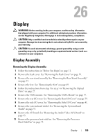
12
Make a note of the camera cables, touch-screen control board cables,
backlight cable, and LVDS cable routing.
NOTE:
The location of the LVDS connector may vary depending on the computer
configuration.
13
Disconnect the cables from the connectors on the system board,
touch-screen control board, AV board, and the converter board.
14
Remove the middle frame. See "Removing the Middle Frame" on page 71.
15
Remove the five screws that secure the chassis to the display assembly.
16
Remove the 13 screws that secure the chassis to the display bezel.
1
touch-screen control board cables
(optional) (2)
2
camera cable
3
IR receiver cable (optional)
4
LVDS cable
5
backlight cable
5
2
1
4
3