Dell Inspiron One 2320 Owners Manual - Page 118
Replacing the Camera Module
 |
View all Dell Inspiron One 2320 manuals
Add to My Manuals
Save this manual to your list of manuals |
Page 118 highlights
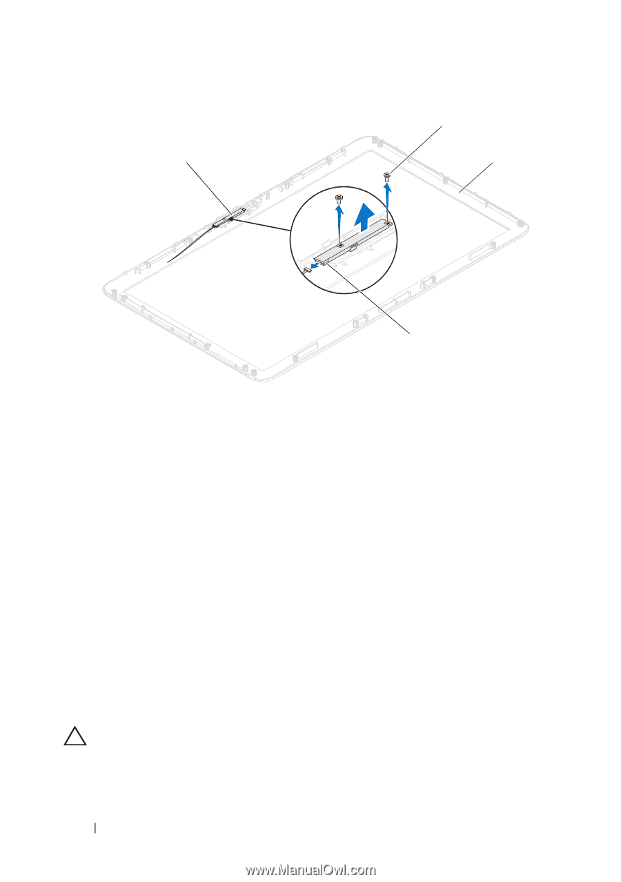
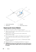
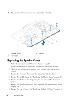
2 1 3 4 1 camera-module assembly 3 display bezel 2 screws (2) 4 camera-cable connector Replacing the Camera Module 1 Follow the instructions in "Before You Begin" on page 11. 2 Align the screw holes on the camera module with the screw holes on the camera-module assembly. 3 Replace the two screws that secure the camera module to the camera-module assembly. 4 Place the camera-module assembly on the display bezel and connect the camera cable to the camera-cable connector on the camera-module assembly 5 Follow the instructions from step 2 to step 17 in "Replacing the Display Assembly" on page 111. 6 Replace the back cover. See "Replacing the Back Cover" on page 21. CAUTION: Before turning on the computer, replace all screws and ensure that no stray screws remain inside the computer. Failure to do so may result in damage to the computer. 118 Camera
-
 1
1 -
2
-
3
-
4
-
5
-
6
-
7
-
8
-
9
-
10
-
11
-
12
-
13
-
14
-
15
-
16
-
17
-
18
-
19
-
20
-
21
-
22
-
23
-
24
-
25
-
26
-
27
-
28
-
29
-
30
-
31
-
32
-
33
-
34
-
35
-
36
-
37
-
38
-
39
-
40
-
41
-
42
-
43
-
44
-
45
-
46
-
47
-
48
-
49
-
50
-
51
-
52
-
53
-
54
-
55
-
56
-
57
-
58
-
59
-
60
-
61
-
62
-
63
-
64
-
65
-
66
-
67
-
68
-
69
-
70
-
71
-
72
-
73
-
74
-
75
-
76
-
77
-
78
-
79
-
80
-
81
-
82
-
83
-
84
-
85
-
86
-
87
-
88
-
89
-
90
-
91
-
92
-
93
-
94
-
95
-
96
-
97
-
98
-
99
-
100
-
101
-
102
-
103
-
104
-
105
-
106
-
107
-
108
-
109
-
110
-
111
-
112
-
 113
113 -
 114
114 -
 115
115 -
 116
116 -
 117
117 -
 118
118 -
 119
119 -
 120
120 -
 121
121 -
 122
122 -
 123
123 -
124
-
125
-
126
-
127
-
128
-
129
-
130
-
131
-
132
-
133
-
134
-
135
-
136
-
137
-
138
 |
 |