Dell Inspiron One 2320 Owners Manual - Page 111
Replacing the Display Assembly, Place the display assembly on the chassis.
 |
View all Dell Inspiron One 2320 manuals
Add to My Manuals
Save this manual to your list of manuals |
Page 111 highlights
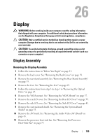
1 2 1 screws (5) 2 screws (13) 17 Using your fingertips, carefully pry up the inside edge of the display assembly. 18 Lift the chassis away from the display assembly. 19 Release the camera cables, touch-screen control board cables, backlight cable, and LVDS cable through the slots on the chassis. Replacing the Display Assembly 1 Follow the instructions in "Before You Begin" on page 11. 2 Place the display assembly on the chassis. 3 Slide the camera cables, touch-screen control board cables, backlight cable and LVDS cable through the slots on the chassis. Display 111
-
 1
1 -
2
-
3
-
4
-
5
-
6
-
7
-
8
-
9
-
10
-
11
-
12
-
13
-
14
-
15
-
16
-
17
-
18
-
19
-
20
-
21
-
22
-
23
-
24
-
25
-
26
-
27
-
28
-
29
-
30
-
31
-
32
-
33
-
34
-
35
-
36
-
37
-
38
-
39
-
40
-
41
-
42
-
43
-
44
-
45
-
46
-
47
-
48
-
49
-
50
-
51
-
52
-
53
-
54
-
55
-
56
-
57
-
58
-
59
-
60
-
61
-
62
-
63
-
64
-
65
-
66
-
67
-
68
-
69
-
70
-
71
-
72
-
73
-
74
-
75
-
76
-
77
-
78
-
79
-
80
-
81
-
82
-
83
-
84
-
85
-
86
-
87
-
88
-
89
-
90
-
91
-
92
-
93
-
94
-
95
-
96
-
97
-
98
-
99
-
100
-
101
-
102
-
103
-
104
-
105
-
 106
106 -
 107
107 -
 108
108 -
 109
109 -
 110
110 -
 111
111 -
 112
112 -
 113
113 -
 114
114 -
 115
115 -
 116
116 -
117
-
118
-
119
-
120
-
121
-
122
-
123
-
124
-
125
-
126
-
127
-
128
-
129
-
130
-
131
-
132
-
133
-
134
-
135
-
136
-
137
-
138
 |
 |

Display
111
17
Using your fingertips, carefully pry up the inside edge of the display
assembly.
18
Lift the chassis away from the display assembly.
19
Release the camera cables, touch-screen control board cables, backlight
cable, and LVDS cable through the slots on the chassis.
Replacing the Display Assembly
1
Follow the instructions in "Before You Begin" on page 11.
2
Place the display assembly on the chassis.
3
Slide the camera cables, touch-screen control board cables, backlight cable
and LVDS cable through the slots on the chassis.
1
screws (5)
2
screws (13)
1
2