Dell Latitude E6430 Owner's Manual - Page 34
Installing the Power LED Board, Removing the Modem Card
 |
View all Dell Latitude E6430 manuals
Add to My Manuals
Save this manual to your list of manuals |
Page 34 highlights
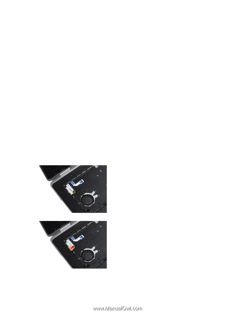
Installing the Power LED Board 1. Place the power LED board in its compartment in the display assembly. 2. Tighten the screw to secure the LED board to the display assembly. 3. Connect the power LED board cable to the display assembly. 4. Install: a) display panel b) display bezel c) display assembly d) keyboard e) keyboard trim f) bluetooth module g) hard drive h) base cover i) battery 5. Follow the procedures in After Working Inside Your Computer. Removing the Modem Card 1. Follow the procedures in Before Working Inside Your Computer. 2. Remove: a) battery b) base cover c) keyboard trim d) keyboard 3. Remove the screw that secures the modem card to the computer. 4. Pull out the tab from underneath the palmrest assembly. 34
-
 1
1 -
2
-
3
-
4
-
5
-
6
-
7
-
8
-
9
-
10
-
11
-
12
-
13
-
14
-
15
-
16
-
17
-
18
-
19
-
20
-
21
-
22
-
23
-
24
-
25
-
26
-
27
-
28
-
 29
29 -
 30
30 -
 31
31 -
 32
32 -
 33
33 -
 34
34 -
 35
35 -
 36
36 -
 37
37 -
 38
38 -
 39
39 -
40
-
41
-
42
-
43
-
44
-
45
-
46
-
47
-
48
-
49
-
50
-
51
-
52
-
53
-
54
-
55
-
56
-
57
-
58
-
59
-
60
-
61
-
62
-
63
-
64
-
65
-
66
-
67
-
68
-
69
-
70
-
71
-
72
-
73
-
74
-
75
-
76
-
77
-
78
-
79
-
80
-
81
-
82
-
83
 |
 |
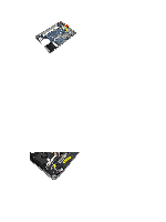
Installing the Power LED Board
1.
Place the power LED board in its compartment in the display assembly.
2.
Tighten the screw to secure the LED board to the display assembly.
3.
Connect the power LED board cable to the display assembly.
4.
Install:
a)
display panel
b)
display bezel
c)
display assembly
d)
keyboard
e)
keyboard trim
f)
bluetooth module
g)
hard drive
h)
base cover
i)
battery
5.
Follow the procedures in
After Working Inside Your Computer
.
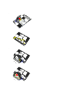
Removing the Modem Card
1.
Follow the procedures in
Before Working Inside Your Computer
.
2.
Remove:
a)
battery
b)
base cover
c)
keyboard trim
d)
keyboard
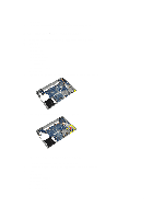
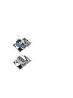
3.
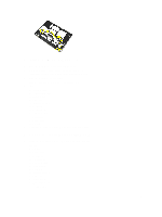
Remove the screw that secures the modem card to the computer.
4.
Pull out the tab from underneath the palmrest assembly.
34