Dell Latitude E6430 Owner's Manual - Page 55
Installing the LVDS and Camera Cable, display panel
 |
View all Dell Latitude E6430 manuals
Add to My Manuals
Save this manual to your list of manuals |
Page 55 highlights
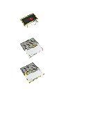
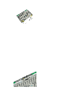
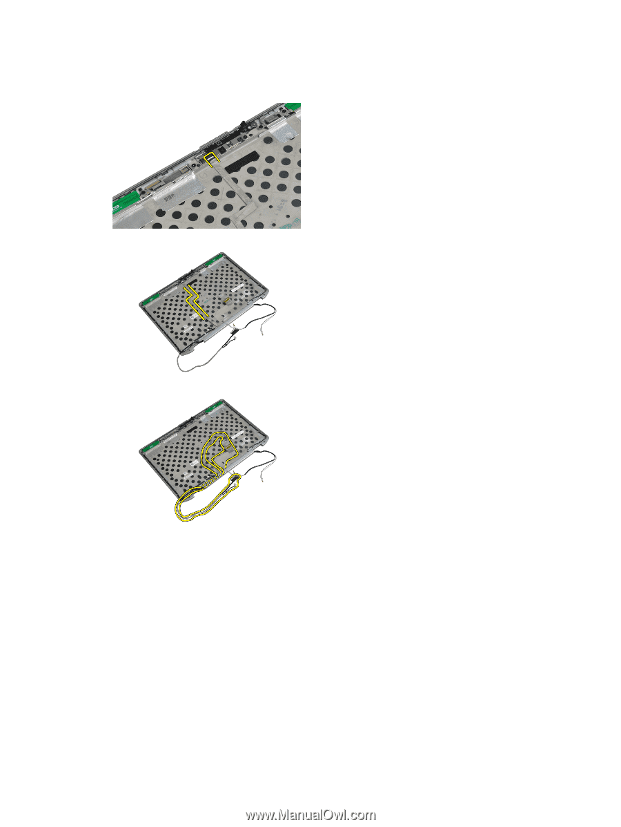
j) display hinges 3. Disconnect the LVDS and camera cable from the camera. 4. Peel back the adhesives securing the LVDS and camera cable to the display assembly. 5. Remove the LVDS and camera cable from the display assembly. Installing the LVDS and Camera Cable 1. Route the LVDS and camera cable on the display assembly. 2. Fix the adhesive the tape to secure the cable. 3. Connect the LVDS and camera cable to the camera. 4. Install: a) display hinges b) display panel c) display bezel d) display assembly e) keyboard f) keyboard trim g) bluetooth card 55
-
 1
1 -
2
-
3
-
4
-
5
-
6
-
7
-
8
-
9
-
10
-
11
-
12
-
13
-
14
-
15
-
16
-
17
-
18
-
19
-
20
-
21
-
22
-
23
-
24
-
25
-
26
-
27
-
28
-
29
-
30
-
31
-
32
-
33
-
34
-
35
-
36
-
37
-
38
-
39
-
40
-
41
-
42
-
43
-
44
-
45
-
46
-
47
-
48
-
49
-
 50
50 -
 51
51 -
 52
52 -
 53
53 -
 54
54 -
 55
55 -
 56
56 -
 57
57 -
 58
58 -
 59
59 -
 60
60 -
61
-
62
-
63
-
64
-
65
-
66
-
67
-
68
-
69
-
70
-
71
-
72
-
73
-
74
-
75
-
76
-
77
-
78
-
79
-
80
-
81
-
82
-
83
 |
 |
j)
display hinges
3.
Disconnect the LVDS and camera cable from the camera.
4.
Peel back the adhesives securing the LVDS and camera cable to the display assembly.
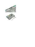
5.
Remove the LVDS and camera cable from the display assembly.
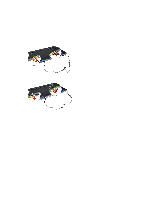
Installing the LVDS and Camera Cable
1.
Route the LVDS and camera cable on the display assembly.
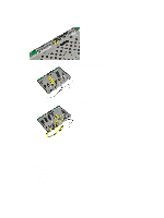
2.
Fix the adhesive the tape to secure the cable.
3.
Connect the LVDS and camera cable to the camera.
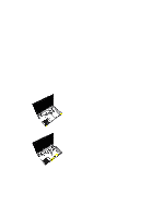
4.
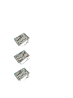
Install:
a)
display hinges
b)
display panel
c)
display bezel
d)
display assembly
e)
keyboard
f)
keyboard trim
g)
bluetooth card
55