Dell OptiPlex 7090 Tower Service Manual
Dell OptiPlex 7090 Tower Manual
 |
View all Dell OptiPlex 7090 Tower manuals
Add to My Manuals
Save this manual to your list of manuals |
Dell OptiPlex 7090 Tower manual content summary:
- Dell OptiPlex 7090 Tower | Service Manual - Page 1
OptiPlex 7090 Tower Service Manual Regulatory Model: D28M Regulatory Type: D28M005 May 2021 Rev. A00 - Dell OptiPlex 7090 Tower | Service Manual - Page 2
of data and tells you how to avoid the problem. WARNING: A WARNING indicates a potential for property damage, personal injury, or death. © 2021 Dell Inc. or its subsidiaries. All rights reserved. Dell, EMC, and other trademarks are trademarks of Dell Inc. or its subsidiaries. Other trademarks may be - Dell OptiPlex 7090 Tower | Service Manual - Page 3
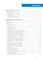
Chapter 1: Working inside your computer 6 Safety instructions...6 Before working inside your computer...6 Safety precautions...7 Electrostatic discharge-ESD protection...7 ESD field service kit ...8 Transporting sensitive components...9 After working inside your computer...9 Chapter 2: Removing and - Dell OptiPlex 7090 Tower | Service Manual - Page 4
the speaker...58 Power button...59 Removing the power button...59 Installing the power button...60 Power-supply unit...61 Removing the power-supply unit...61 Installing the power-supply unit...63 Removing the power-supply unit (For systems with powered GPU 65 Installing the power-supply unit (For - Dell OptiPlex 7090 Tower | Service Manual - Page 5
system setup password 97 Chapter 5: Troubleshooting...99 SupportAssist diagnostics...99 Diagnostic LED behavior...99 Recovering the operating system...100 Updating the BIOS in Windows...101 Updating the BIOS using the USB drive in Windows 101 Backup media and recovery options...101 WiFi power - Dell OptiPlex 7090 Tower | Service Manual - Page 6
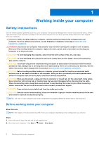
and the contacts. CAUTION: You should only perform troubleshooting and repairs as authorized or directed by the Dell technical assistance team. Damage due to servicing that is not authorized by Dell is not covered by your warranty. See the safety instructions that is shipped with the product or at - Dell OptiPlex 7090 Tower | Service Manual - Page 7
shut-down instructions. 3. Disconnect your computer and all power. ● Disconnect all network cables, telephone, and telecommunications lines from the system. ● Use an ESD field service kit when working inside any desktop problems or a shortened product life span. As the industry pushes for lower power - Dell OptiPlex 7090 Tower | Service Manual - Page 8
troubleshoot service kit The unmonitored Field Service kit is the most commonly used service kit. Each Field Service service service Service service Service desktop or portable environment. Servers are typically installed in a rack within a data center; desktops Dell, it is critical to place - Dell OptiPlex 7090 Tower | Service Manual - Page 9
servicing Dell products. In addition, it is critical that technicians keep sensitive parts separate from all insulator parts while performing service working inside your computer About this task CAUTION: Leaving stray or loose screws inside your computer may severely damage your computer. Steps 1. - Dell OptiPlex 7090 Tower | Service Manual - Page 10
correct screw type is restored when the component is replaced. NOTE: Some computers have magnetic surfaces. Ensure that the screws are not left attached to drive M2x3.5 1 WLAN card M2x3.5 1 Power supply unit / Power-supply unit with #6-32 3 powered GPU 125 W heat-sink assembly #6-32 ( - Dell OptiPlex 7090 Tower | Service Manual - Page 11
Table 1. Screw list (continued) Component Processor fan and 65 W heat-sink assembly VR heat sink System board Screw type #6-32 (Captive) #6-32 (Captive) #6-32 M2x4 Quantity 4 2 9 1 Image Major components of your system 1. Side cover 2. 3.5-inch hard-drive assembly 3. Optical Disk Drive - Dell OptiPlex 7090 Tower | Service Manual - Page 12
. Speaker 15. Intrusion switch 16. Power Supply Unit 17. 2.5-inch hard-disk drive assembly NOTE: Dell provides a list of components and their Dell sales representative for purchase options. Side cover Removing the side cover Prerequisites 1. Follow the procedure in before working inside your computer - Dell OptiPlex 7090 Tower | Service Manual - Page 13
Steps 1. Slide the release latch to release the cover from the computer. 2. Slide the side cover towards the rear of the computer and lift the cover away from the computer. Installing the side cover Prerequisites If you are replacing a component, remove the existing component before performing the - Dell OptiPlex 7090 Tower | Service Manual - Page 14
1. Locate the side cover slot on your computer. 2. Align the tabs on the side cover with the slots on the chassis. 3. Slide the side cover towards the front of the computer to install it. 4. The release latch automatically locks the side cover to the computer. Next steps 1. Follow the procedure in - Dell OptiPlex 7090 Tower | Service Manual - Page 15
the chassis. 2. Press the bezel until the tabs clicks into place. Next steps 1. Install the side cover. 2. Follow the procedure in after working inside your computer. Removing the front bezel Prerequisites 1. Follow the procedure in before working inside your - Dell OptiPlex 7090 Tower | Service Manual - Page 16
pull the front bezel and gently rotate to release the other tabs on the bezel from the slots in the computer chassis. 3. Remove the front bezel from the computer. Hard-drive assembly Removing the primary 2.5-inch hard-drive assembly Prerequisites 1. Follow the procedure in before working inside your - Dell OptiPlex 7090 Tower | Service Manual - Page 17
the hard-drive data and power cables from the connectors on the 2.5-inch hard-drive module. 2. Press the release tabs on both the sides of the hard-drive bracket to release it from the slots on the computer chassis. 3. Lift the hard-drive assembly from the computer. NOTE: Note the orientation of - Dell OptiPlex 7090 Tower | Service Manual - Page 18
Steps 1. Disconnect the power cable and the black hard drive data cable from the connectors on drive assembly out of the hard-disk drive bracket. 3. Lift the hard-disk drive assembly from the computer. NOTE: The orientation of the hard-disk drive so that you can replace it correctly. Removing the - Dell OptiPlex 7090 Tower | Service Manual - Page 19
About this task The following images indicate the location of the hard-disk drive bracket and provide a visual representation of the removal procedure. Steps 1. Pull one side of the hard-disk drive bracket to disengage the pins on the bracket from the slots on the drive. 2. Lift the hard-disk drive - Dell OptiPlex 7090 Tower | Service Manual - Page 20
-disk drive or 2.5-inch secondary hard-disk drive. 2. Install the side cover. 3. Follow the procedure in after working inside your computer. Installing the secondary 2.5-inch hard-disk drive assembly Prerequisites If you are replacing a component, remove the existing component before performing the - Dell OptiPlex 7090 Tower | Service Manual - Page 21
Steps 1. Insert the hard-disk drive assembly into the slot on the computer until it clicks into place. 2. For 2.5-inch hard-disk drive set as secondary, connect the black hard drive data cable and power cable to the connectors on the 2.5-inch hard drive. Next steps 1. Install the side cover. 2. - Dell OptiPlex 7090 Tower | Service Manual - Page 22
until it clicks into place. 2. Connect the hard-drive data and power cables to the connectors on the 2.5-inch hard-drive module. Next steps 1. Install the side cover. 2. Follow the procedure in after working inside your computer. 3.5 in. hard-drive assembly Removing the 3.5-inch hard-disk drive - Dell OptiPlex 7090 Tower | Service Manual - Page 23
a visual representation of the removal procedure. Steps 1. Disconnect the data and power cables from the 3.5-inch hard-disk drive module. 2. Push the securing Prerequisites 1. Follow the procedure in before working inside your computer. 2. Remove the side cover. 3. Remove the 3.5-inch hard- - Dell OptiPlex 7090 Tower | Service Manual - Page 24
About this task The following image indicates the location of the 3.5-inch hard-disk drive bracket and provides a visual representation of the removal procedure. Steps 1. Pry one side of the hard-disk drive bracket edge to release the tabs on the bracket from the slots on the hard-disk drive. 2. - Dell OptiPlex 7090 Tower | Service Manual - Page 25
Next steps 1. Install the 3.5-inch hard-disk drive assembly. 2. Install the side cover. 3. Follow the procedure in after working inside your computer. Installing the 3.5-inch hard-disk drive assembly Prerequisites If you are replacing a component, remove the existing component before performing the - Dell OptiPlex 7090 Tower | Service Manual - Page 26
. 2. Replace the EMI shield on the chassis. 3. Align the hard-disk drive assembly with the tabs on the chassis. 4. Route the power cable and the data cable through the routing guides on the hard-disk drive assembly and connect the cables to the hard-disk drive. Next steps 1. Install the side cover - Dell OptiPlex 7090 Tower | Service Manual - Page 27
. Removing the M.2 2280 PCIe solid-state drive Prerequisites 1. Follow the procedure in before working inside your computer. 2. Remove the side cover. About this task The following images indicate the location of the solid-state drive and provide a visual representation of the removal - Dell OptiPlex 7090 Tower | Service Manual - Page 28
Steps 1. Remove the screw (M2x3.5) that secures the solid-state drive to the system board. 2. Slide and lift the solid-state drive off the system board. NOTE: Repeat the above procedure for removing the other solid-state drive. 28 Removing and installing components - Dell OptiPlex 7090 Tower | Service Manual - Page 29
Installing the M.2 2280 PCIe solid-state drive Prerequisites If you are replacing a component, remove the existing component before performing the installation procedure. About this task The following image indicates the location of the solid-state drive and provides a visual representation of the - Dell OptiPlex 7090 Tower | Service Manual - Page 30
cover. 2. Follow the procedure in after working inside your computer. Removing the M.2 2230 PCIe solid-state drive Prerequisites 1. Follow the procedure in before working inside your computer. 2. Remove the side cover. About this task The following - Dell OptiPlex 7090 Tower | Service Manual - Page 31
Memory module Removing the memory module Prerequisites 1. Follow the procedure in before working inside your computer. 2. Remove the side cover. About this task The following images indicate the location of the memory module and provide a visual representation of the removal procedure. - Dell OptiPlex 7090 Tower | Service Manual - Page 32
side cover. 2. Follow the procedure in after working inside your computer. Processor fan and heat-sink assembly Removing the processor fan and sink assembly Prerequisites 1. Follow the procedure in before working inside your computer. WARNING: The heat sink may become hot during normal operation. - Dell OptiPlex 7090 Tower | Service Manual - Page 33
fan and heat-sink assembly from the system board. Removing the processor fan Prerequisites 1. Follow the procedure in before working inside your computer. 2. Remove the side cover. 3. Remove the processor fan and heat-sink assembly. About this task The following images indicate the location of - Dell OptiPlex 7090 Tower | Service Manual - Page 34
Steps 1. Remove the six screws that secure the processor fan to the heat-sink assembly. 2. Lift the processor fan from the heat-sink. 3. Remove the two screws that secure the metal plate to the processor fan. 4. Lift the metal plate away from the processor fan. Installing the processor fan - Dell OptiPlex 7090 Tower | Service Manual - Page 35
1. Install the processor fan and heat-sink assembly. 2. Install the side cover. 3. Follow the procedure in after working inside your computer. Installing the processor fan and 125 W heat-sink assembly Prerequisites If you are replacing a component, remove the existing component before performing - Dell OptiPlex 7090 Tower | Service Manual - Page 36
the processor fan and heat-sink assembly on the processor. NOTE: Ensure that the triangle mark is directed towards the rear side of the computer. 2. In the sequential order (1->2->3->4), tighten the captive screws to secure the processor fan and heat-sink assembly to the system board. NOTE: Tighten - Dell OptiPlex 7090 Tower | Service Manual - Page 37
CAUTION: For maximum cooling of the processor, do not touch the heat transfer areas on the heat sink. The oils in your skin can reduce the heat transfer capability of the thermal grease. 2. Remove the side cover. About this task The following images indicate the location of the processor fan and - Dell OptiPlex 7090 Tower | Service Manual - Page 38
Remove the processor fan and 125 W heat-sink assembly or processor fan and heat-sink assembly. NOTE: The processor might still be hot after the computer is shut down. Allow the processor to cool down before removing it. About this task The following images indicate the location of the processor and - Dell OptiPlex 7090 Tower | Service Manual - Page 39
Steps 1. Press down and push the release lever away from the processor to release it from the securing tab. 2. Lift the lever upward to lift the processor cover. CAUTION: When removing the processor, do not touch any of the pins inside the socket or allow any objects to fall on the pins in the - Dell OptiPlex 7090 Tower | Service Manual - Page 40
fan and 125 W heat-sink assembly or processor fan and heat-sink assembly. 2. Install the side cover. 3. Follow the procedure in after working inside your computer. 40 Removing and installing components - Dell OptiPlex 7090 Tower | Service Manual - Page 41
Graphics card Removing the graphics card Prerequisites 1. Follow the procedure in before working inside your computer. 2. Remove the side cover. About this task The following images indicate the location of the graphics card and provide a visual representation of the removal procedure. - Dell OptiPlex 7090 Tower | Service Manual - Page 42
firmly seated. 3. Lift the pull tab to close the PCIe door. Next steps 1. Install the side cover. 2. Follow the procedure in after working inside your computer. 42 Removing and installing components - Dell OptiPlex 7090 Tower | Service Manual - Page 43
GPU Prerequisites 1. Follow the procedure in before working inside your computer. 2. Remove the side cover. About this task The following images indicate the location of the powered graphical processing unit and provide a visual representation of the removal procedure. Removing and installing - Dell OptiPlex 7090 Tower | Service Manual - Page 44
the cable holder. 3. Press the securing clips on both side of the power-cable holder and slide the powered GPU cable holder out of the computer. 4. Lift the pull tab to open the PCIe door. Installing the powered GPU Prerequisites If you are replacing a component, remove the existing component before - Dell OptiPlex 7090 Tower | Service Manual - Page 45
Steps 1. Align the powered GPU with the PCI-Express card connector on the system board. 2. Using the alignment post, connect the powered GPU in the connector and press down firmly. Ensure that the powered GPU is firmly seated. 3. Lift the pull tab to close the PCIe door. Removing and installing - Dell OptiPlex 7090 Tower | Service Manual - Page 46
GPU cable holder with the triangles on the chassis. 5. Place the powered GPU cable holder on the computer chassis until it clicks to place. 6. Route the power cable through the retention tab on the cable holder. 7. Connect the two power cables, through the slot on the cable holder, to the connector - Dell OptiPlex 7090 Tower | Service Manual - Page 47
Install the side cover. 3. Follow the procedure in after working inside your computer. WLAN card Removing the WLAN card Prerequisites 1. Follow the procedure in before working inside your computer. 2. Remove the side cover. 3. Remove the powered GPU. NOTE: This step is required only if the system is - Dell OptiPlex 7090 Tower | Service Manual - Page 48
About this task The following images indicate the location of the wireless card and provide a visual representation of the removal procedure. Steps 1. Remove the (M2x3.5) screw that secures the WLAN card to the system board. 2. Lift the WLAN card bracket away from the WLAN card. 3. Disconnect the - Dell OptiPlex 7090 Tower | Service Manual - Page 49
screw to secure the plastic tab to the WLAN card. Next steps 1. Install the powered GPU. NOTE: This step is required only if the system is configured with powered GPU. 2. Install the side cover. 3. Follow the procedure in after working inside your computer. Removing and installing components 49 - Dell OptiPlex 7090 Tower | Service Manual - Page 50
Prerequisites 1. Follow the procedure in before working inside your computer. 2. Remove the side cover. About this task The following a visual representation of the removal procedure. Steps 1. Disconnect the data and power cables from the slim ODD. 2. Push the securing tab to release the slim - Dell OptiPlex 7090 Tower | Service Manual - Page 51
Insert the slim ODD assembly into the ODD slot. 2. Slide the slim ODD assembly until it snaps into place. 3. Route the power cable and data cable through the routing guides and connect the cables to the slim ODD. Next steps 1. Install the side cover. 2. Follow the procedure in after working inside - Dell OptiPlex 7090 Tower | Service Manual - Page 52
Slim optical-drive bracket Removing the slim-ODD bracket Prerequisites 1. Follow the procedure in before working inside your computer. 2. Remove the side cover. 3. Remove the slim Optical Disk Drive. About this task The following images indicate the location of the slim-ODD bracket and - Dell OptiPlex 7090 Tower | Service Manual - Page 53
Drive. 2. Install the side cover. 3. Follow the procedure in after working inside your computer. Chassis fan Removing the chassis fan Prerequisites 1. Follow the procedure in before working inside your computer. 2. Remove the side cover. About this task The following image indicates the location of - Dell OptiPlex 7090 Tower | Service Manual - Page 54
Steps 1. Locate the chassis fan. 2. Disconnect the fan cable from the connector on the system board. 3. Gently pull the rubber grommets to release the fan from the chassis. 4. Remove the fan off the chassis. Installing the chassis fan Prerequisites If you are replacing a component, remove the - Dell OptiPlex 7090 Tower | Service Manual - Page 55
. 4. Connect the fan cable to the connector on the system board. Next steps 1. Install the side cover. 2. Follow the procedure in after working inside your computer. Voltage regulator heat sink Removing the VR heat sink Prerequisites 1. Follow the procedure in before working inside your - Dell OptiPlex 7090 Tower | Service Manual - Page 56
WARNING: The heat sink may become hot during normal operation. Allow sufficient time for the heat sink to cool before you touch it. CAUTION: For maximum cooling of the processor, do not touch the heat transfer areas on the heat sink. The oils in your skin can reduce the heat transfer capability of - Dell OptiPlex 7090 Tower | Service Manual - Page 57
Next steps 1. Install the side cover. 2. Follow the procedure in after working inside your computer. Speaker Removing the speaker Prerequisites 1. Follow the procedure in before working inside your computer. 2. Remove the side cover. About this task The following images indicate the location of the - Dell OptiPlex 7090 Tower | Service Manual - Page 58
Steps 1. Disconnect the speaker cable from the connector on the system board. 2. Press the tab and slide the speaker along with the cable from the slot on the chassis. Installing the speaker Prerequisites If you are replacing a component, remove the existing component before performing the - Dell OptiPlex 7090 Tower | Service Manual - Page 59
Next steps 1. Install the side cover. 2. Follow the procedure in after working inside your computer. Power button Removing the power button Prerequisites 1. Follow the procedure in before working inside your computer. 2. Remove the side cover. 3. Remove the front bezel. About this task The following - Dell OptiPlex 7090 Tower | Service Manual - Page 60
on the system board. 2. Press the release tabs on the power-button head and slide the power-button cable out from the front-side chassis of the computer. 3. Pull the power-button cable out from the computer. Installing the power button Prerequisites If you are replacing a component, remove the - Dell OptiPlex 7090 Tower | Service Manual - Page 61
bezel. 2. Install the side cover. 3. Follow the procedure in after working inside your computer. Power-supply unit Removing the power-supply unit Prerequisites 1. Follow the procedure in before working inside your computer. 2. Remove the side cover. 3. Remove the processor fan and heat-sink assembly - Dell OptiPlex 7090 Tower | Service Manual - Page 62
About this task The following images indicate the location of the power-supply unit and provide a visual representation of the removal procedure. 62 Removing and installing components - Dell OptiPlex 7090 Tower | Service Manual - Page 63
1. Lay the computer on the right side. 2. Disconnect the power cables from the system board and unroute them from the routing guides on the chassis. 3. Remove the three (#6-32) screws that secure the power-supply unit to the chassis. 4. Press the securing clip and slide the power-supply unit away - Dell OptiPlex 7090 Tower | Service Manual - Page 64
64 Removing and installing components - Dell OptiPlex 7090 Tower | Service Manual - Page 65
the routing guides on the chassis and connect the power cables to their respective connectors on the system board. Next steps 1. Install the processor fan and heat-sink assembly. 2. Install the side cover. 3. Follow the procedure in after working inside your computer. Removing the power-supply unit - Dell OptiPlex 7090 Tower | Service Manual - Page 66
all cables as you remove them so that you can route them correctly while you are replacing the power-supply unit. About this task The following images indicate the location of the power-supply unit and provides a visual representation of the removal procedure. 66 Removing and installing components - Dell OptiPlex 7090 Tower | Service Manual - Page 67
Removing and installing components 67 - Dell OptiPlex 7090 Tower | Service Manual - Page 68
the securing clips on both side of the cable holder and slide the powered GPU cable holder out of the computer. 5. Unroute the cables from the routing guides on the chassis. 6. Remove the three (#6-32) screws that secure the power-supply unit to the chassis. 7. Press the securing clip and slide the - Dell OptiPlex 7090 Tower | Service Manual - Page 69
Removing and installing components 69 - Dell OptiPlex 7090 Tower | Service Manual - Page 70
the securing tab snaps into position. 2. Replace the three screws (#6-32) that secure the power-supply unit to the chassis. 3. Route the power cable through the routing guides on the chassis and connect the power cables to their respective connectors on the system board. 70 Removing and installing - Dell OptiPlex 7090 Tower | Service Manual - Page 71
GPU cable holder with the triangles on the chassis. 5. Place the powered GPU cable holder on the computer chassis until it clicks to place. 6. Route the power cable through the retention tab on the cable holder. 7. Connect the two power cables, through the slot on the cable holder, to the connector - Dell OptiPlex 7090 Tower | Service Manual - Page 72
cable to the connector on the system board. Next steps 1. Install the side cover. 2. Follow the procedure in after working inside your computer. Optional I/O modules (Type C/ HDMI/VGA/DP/Serial) Removing optional I/O modules (Type-C/HDMI/VGA/DP/Serial) Prerequisites 1. Follow the procedure in before - Dell OptiPlex 7090 Tower | Service Manual - Page 73
chassis. 2. Disconnect the I/O-module cable from the connector on the system board. 3. Remove the I/O module from the computer. Installing optional I/O modules (Type-C/HDMI/VGA/DP/Serial) Prerequisites If you are replacing a component, remove the existing component before performing the installation - Dell OptiPlex 7090 Tower | Service Manual - Page 74
the system board Prerequisites 1. Follow the procedure in before working inside your computer. NOTE: Your computer's Service Tag is stored in the system board. You must enter the Service Tag in the BIOS setup program after you replace the system board. NOTE: Replacing the system board removes - Dell OptiPlex 7090 Tower | Service Manual - Page 75
the M.2 2230 SSD/M.2 2280 SSD. 7. Remove the coin-cell battery. 8. Remove the graphics card. 9. Remove the powered GPU. NOTE: This step is required only if the system is configured with powered GPU. 10. Remove the speaker. 11. Remove the intrusion switch. 12. Remove the VR heatsink. 13. Remove the - Dell OptiPlex 7090 Tower | Service Manual - Page 76
10. Two SATA1/2 connector (black) 11. SATA3 connector (white) 12. SATA power cable connector 13. Coin-cell battery 14. M.2 WLAN connector 15. System power connector 16. Internal speaker connector 17. Thunderbolt header 18. M.2 PCIe SSD connector 19. PCIe x4 (Slot4) 20. PCI (Slot3) 21. PCIe x16 ( - Dell OptiPlex 7090 Tower | Service Manual - Page 77
Removing and installing components 77 - Dell OptiPlex 7090 Tower | Service Manual - Page 78
the (#6-32) screw that secures the front I/O-bracket to the chassis. 2. Slide and remove the front I/O-bracket from the chassis. 3. Disconnect the power cables that are connected to the system board and unroute them from the routing guides on the chassis. 78 Removing and installing components - Dell OptiPlex 7090 Tower | Service Manual - Page 79
About this task The following image indicates the connectors on your system board. 1. CPU power connector 2. Processor fan connector 3. Memory module connector 4. Power button connector 5. Remote power switch connector 6. SD card reader connector 7. SATA0 connector (blue) 8. M.2 PCIe SSD connector - Dell OptiPlex 7090 Tower | Service Manual - Page 80
18. M.2 PCIe SSD connector 19. PCIe x4 (Slot4) 20. PCI (Slot3) 21. PCIe x16 (Slot2) 22. PCIE x1 (Slot1) 23. System fan connector 24. Chassis Intrusion Detection connector 25. Type-C connector 26. Processor socket 27. Video connector The following images indicate the location of the system board and - Dell OptiPlex 7090 Tower | Service Manual - Page 81
Removing and installing components 81 - Dell OptiPlex 7090 Tower | Service Manual - Page 82
Steps 1. Slide the front I/O-ports on the system board into the front I/O-slots on the chassis and align the screw holes on the system board with the screw holes on the chassis. 2. Replace the (M2x4) screw to secure the system board to the chassis. 3. Replace the eight screws (#6-32) that secure the - Dell OptiPlex 7090 Tower | Service Manual - Page 83
cable through the routing guides on the chassis and connect the power cables to their respective connectors on the in after working inside your computer. NOTE: Your computer's Service Tag is stored in the system board. You must enter the Service Tag in the BIOS setup program after you replace - Dell OptiPlex 7090 Tower | Service Manual - Page 84
3 Software This chapter details the supported operating systems along with instructions on how to install the drivers. Drivers and downloads When troubleshooting, downloading or installing drivers it is recommended that you read the Dell Knowledge Based article, Drivers and Downloads FAQ 000123347. - Dell OptiPlex 7090 Tower | Service Manual - Page 85
program, it is recommended that you write down the BIOS Setup program screen information for future reference. Use the BIOS Setup program for the following purposes: ● Get information about the hardware installed in your computer, such as the amount of RAM and the size of the hard drive. ● Change - Dell OptiPlex 7090 Tower | Service Manual - Page 86
, the items that are listed in this section may or may not appear. Table 3. System setup options-System information menu Overview OptiPlex 7090 Tower BIOS Version Displays the BIOS version number. Service Tag Displays the Service Tag of the computer. Asset Tag Displays the Asset Tag of the - Dell OptiPlex 7090 Tower | Service Manual - Page 87
Slot 2 Displays the SATA hard drive information of the computer. Slot 3 Displays the SATA hard drive information of the computer. Slot 4 Displays the SATA hard drive information of the computer. Table 4. System setup options-Boot Configuration menu Boot Configuration Boot Sequence Boot Mode - Dell OptiPlex 7090 Tower | Service Manual - Page 88
maintenance. By default, the Disabled option is enabled. Table 6. System setup options-Storage menu Storage SATA Operation Enable or disable the operating mode Self-Monitoring, Analysis, and Reporting Technology (SMART) during computer startup. By default, the Enable SMART Reporting option is - Dell OptiPlex 7090 Tower | Service Manual - Page 89
Digital (SD) Card Read-Only Mode option is not enabled. Table 7. System setup options-Display menu Display Multi-Display Enable Multi-Display Enable or disable the Enable Multi-Display buttons on the computer. By default, the option is enabled. Primary Display Video Primary Display Determines - Dell OptiPlex 7090 Tower | Service Manual - Page 90
setup options-Power menu Power USB PowerShare Enable USB PowerShare Enable or disable the USB PowerShare. By default, the Enable USB PowerShare option is enabled USB Wake Support Enable USB Wake Support When enabled, you can use the USB devices like a mouse or keyboard to wake your computer - Dell OptiPlex 7090 Tower | Service Manual - Page 91
permanently disable the BIOS module interface of the optional Absolute Persistence Module service from Absolute software. By default, the Enable Absolute option is enabled. UEFI Boot Path Security Controls whether or not the computer will prompt the user to enter the admin password (if set) when - Dell OptiPlex 7090 Tower | Service Manual - Page 92
powered on from the off state. By default, the Disabled option is enabled. Password Changes Enable Non-Admin Password Changes Enable or disable to change computer and hard drive password without the need for admin password. By default, the option is enabled. Admin Setup Lockout Enable Admin Setup - Dell OptiPlex 7090 Tower | Service Manual - Page 93
for Dell OS Recovery Tool. By default, the threshold value is set to 2. Table 13. System setup options-System Management menu System Management Service Tag Asset Tag Wake on LAN/WLAN Display the Service Tag of the computer. Create a computer Asset Tag. Enable or disable the computer to power on - Dell OptiPlex 7090 Tower | Service Manual - Page 94
the option is disabled. Table 17. System setup options-Performance menu Performance Multi Core Support Active Cores Enables to change the number Technology Enables the computer to dynamically adjust processor voltage and core frequency, decreasing average power consumption and heat production. - Dell OptiPlex 7090 Tower | Service Manual - Page 95
.dell.com/support. 2. Click Product support. In the Search support box, enter the Service Tag of your computer, and then click Search. NOTE: If you do not have the Service Tag, use the SupportAssist feature to automatically identify your computer. You can also use the product ID or manually browse - Dell OptiPlex 7090 Tower | Service Manual - Page 96
does not have to be bootable) ● BIOS executable file that you downloaded from the Dell Support website and copied to the root of the USB drive ● AC power adapter that is connected to the computer ● Functional computer battery to flash the BIOS Perform the following steps to perform the BIOS update - Dell OptiPlex 7090 Tower | Service Manual - Page 97
to the BIOS settings of your computer. You can create a system password and a setup password to secure your computer. CAUTION: The password features provide To enter the system setup, press F2 immediately after a power-on or reboot. Steps 1. In the System BIOS or System Setup screen, select Security - Dell OptiPlex 7090 Tower | Service Manual - Page 98
System and/or Setup password, re enter the new password when prompted. If you delete the System and Setup password, confirm the deletion when prompted. 5. Press Esc and a message prompts you to save the changes. 6. Press Y to save the changes and exit from System Setup. The computer restarts. 98 - Dell OptiPlex 7090 Tower | Service Manual - Page 99
are completed successfully ● View error messages that indicate if problems were encountered during the test NOTE: Some tests are meant for specific devices and require user interaction. Ensure that you are present in front of the computer when the diagnostic tests are performed. For more information - Dell OptiPlex 7090 Tower | Service Manual - Page 100
it from the Dell Support website to troubleshoot and fix your computer when it fails to boot into their primary operating system due to software or hardware failures. For more information about the Dell SupportAssist OS Recovery, see Dell SupportAssist OS Recovery User's Guide at www.dell.com - Dell OptiPlex 7090 Tower | Service Manual - Page 101
the instructions on how to conduct a WiFi power cycle: NOTE: Some ISPs (Internet Service Providers) provide a modem/router combo device. Steps 1. Turn off your computer. 2. Turn off the modem. 3. Turn off the wireless router. 4. Wait for 30 seconds. 5. Turn on the wireless router. Troubleshooting - Dell OptiPlex 7090 Tower | Service Manual - Page 102
seconds to drain the flea power. 6. Install the battery. 7. Install the base cover. 8. Connect the power adapter to your computer. 9. Turn on your computer. NOTE: For more information about performing a hard reset, see the knowledge base article 000130881 at www.dell.com/support. 102 Troubleshooting - Dell OptiPlex 7090 Tower | Service Manual - Page 103
more about your computer through videos, manuals and documents. Your Dell computer is uniquely identified by a Service Tag or Express Service Code. To view relevant support resources for your Dell computer, enter the Service Tag or Express Service Code at www.dell.com/support. For more information
-
 1
1 -
 2
2 -
 3
3 -
 4
4 -
 5
5 -
 6
6 -
 7
7 -
8
-
9
-
10
-
11
-
12
-
13
-
14
-
15
-
16
-
17
-
18
-
19
-
20
-
21
-
22
-
23
-
24
-
25
-
26
-
27
-
28
-
29
-
30
-
31
-
32
-
33
-
34
-
35
-
36
-
37
-
38
-
39
-
40
-
41
-
42
-
43
-
44
-
45
-
46
-
47
-
48
-
49
-
50
-
51
-
52
-
53
-
54
-
55
-
56
-
57
-
58
-
59
-
60
-
61
-
62
-
63
-
64
-
65
-
66
-
67
-
68
-
69
-
70
-
71
-
72
-
73
-
74
-
75
-
76
-
77
-
78
-
79
-
80
-
81
-
82
-
83
-
84
-
85
-
86
-
87
-
88
-
89
-
90
-
91
-
92
-
93
-
94
-
95
-
96
-
97
-
98
-
99
-
100
-
101
-
102
-
103
 |
 |

OptiPlex 7090 Tower
Service Manual
Regulatory Model: D28M
Regulatory Type: D28M005
May 2021
Rev. A00