Dell OptiPlex 7090 Tower Service Manual - Page 79
Installing the system board, M.2 WLAN connector
 |
View all Dell OptiPlex 7090 Tower manuals
Add to My Manuals
Save this manual to your list of manuals |
Page 79 highlights
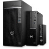
4. Remove the eight (#6-32) screws that secure the system board to the chassis. 5. Remove the (M2x4) screw that secures the system board to the chassis. 6. Lift the system board at an angle and remove the system board off the chassis. Installing the system board Prerequisites If you are replacing a component, remove the existing component before performing the installation procedure. About this task The following image indicates the connectors on your system board. 1. CPU power connector 2. Processor fan connector 3. Memory module connector 4. Power button connector 5. Remote power switch connector 6. SD card reader connector 7. SATA0 connector (blue) 8. M.2 PCIe SSD connector 9. Internal USB connector 10. Two SATA1/2 connector (black) 11. SATA3 connector (white) 12. SATA power cable connector 13. Coin-cell battery 14. M.2 WLAN connector 15. System power connector 16. Internal speaker connector 17. Thunderbolt header Removing and installing components 79
-
 1
1 -
2
-
3
-
4
-
5
-
6
-
7
-
8
-
9
-
10
-
11
-
12
-
13
-
14
-
15
-
16
-
17
-
18
-
19
-
20
-
21
-
22
-
23
-
24
-
25
-
26
-
27
-
28
-
29
-
30
-
31
-
32
-
33
-
34
-
35
-
36
-
37
-
38
-
39
-
40
-
41
-
42
-
43
-
44
-
45
-
46
-
47
-
48
-
49
-
50
-
51
-
52
-
53
-
54
-
55
-
56
-
57
-
58
-
59
-
60
-
61
-
62
-
63
-
64
-
65
-
66
-
67
-
68
-
69
-
70
-
71
-
72
-
73
-
 74
74 -
 75
75 -
 76
76 -
 77
77 -
 78
78 -
 79
79 -
 80
80 -
 81
81 -
 82
82 -
 83
83 -
 84
84 -
85
-
86
-
87
-
88
-
89
-
90
-
91
-
92
-
93
-
94
-
95
-
96
-
97
-
98
-
99
-
100
-
101
-
102
-
103
 |
 |
