Dell OptiPlex GX150 User Guide - Page 52
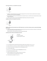
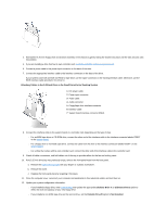
Removing the Hard Drive in the Small Mini-Tower System
 |
View all Dell OptiPlex GX150 manuals
Add to My Manuals
Save this manual to your list of manuals |
Page 52 highlights
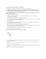
Removing the Hard Drive in the Small Mini-Tower System 7. If necessary, attach the bracket rails to the new hard drive by aligning the four screw holes of the drive and bracket and then inserting and tightening the screws that came with your upgrade kit. 8. If you are installing a new drive, ensure that side bracket rails are attached. If they are not, install the extra set of bracket rails that are located inside the hard drive bay. 9. Install the hard drive bracket in the chassis by gently sliding the bracket into place until you hear it securely click. Installing a Hard Drive in the Small Mini-Tower System NOTICE: You must match the colored strip on the EIDE cable with pin 1 on the drive's interface connector to avoid possible damage to your system. 10. Connect a power cable to the power input connector on the back of the drive, and connect one of the device connectors on the EIDE cable to the 40-pin interface connector on the back of the hard drive. Check all connectors to be certain that they are properly cabled and firmly seated. Attaching Hard Drive Cables in the Small Mini-Tower System 1 EIDE cable 2 Drive power connector 3 System board IDE1 connector 11. If it is not already connected, connect the other end of the EIDE cable to the IDE1 connector on the system board. 12. Close the computer cover, reconnect your computer and peripherals to their electrical outlets, and turn them on. 13. If the drive you just installed is the primary drive, insert a bootable floppy into drive A. 14. Turn on the computer system. 15. Enter system setup, and update the appropriate Primary Drive option (0 or 1). 16. Exit system setup, and reboot the system. 17. Partition and logically format your drive before you proceed to the next step. See the documentation for your operating system for instructions. 18. Test the hard drive by running the Dell Diagnostics.
-
 1
1 -
2
-
3
-
4
-
5
-
6
-
7
-
8
-
9
-
10
-
11
-
12
-
13
-
14
-
15
-
16
-
17
-
18
-
19
-
20
-
21
-
22
-
23
-
24
-
25
-
26
-
27
-
28
-
29
-
30
-
31
-
32
-
33
-
34
-
35
-
36
-
37
-
38
-
39
-
40
-
41
-
42
-
43
-
44
-
45
-
46
-
 47
47 -
 48
48 -
 49
49 -
 50
50 -
 51
51 -
 52
52 -
 53
53 -
 54
54 -
 55
55 -
 56
56 -
 57
57 -
58
-
59
-
60
-
61
-
62
-
63
-
64
-
65
-
66
-
67
-
68
-
69
-
70
-
71
-
72
-
73
-
74
-
75
-
76
-
77
-
78
-
79
-
80
-
81
-
82
-
83
-
84
-
85
-
86
-
87
-
88
-
89
-
90
-
91
-
92
-
93
-
94
-
95
-
96
-
97
-
98
-
99
-
100
-
101
-
102
-
103
-
104
-
105
-
106
-
107
-
108
-
109
-
110
-
111
-
112
-
113
-
114
-
115
-
116
-
117
-
118
-
119
-
120
-
121
-
122
-
123
-
124
-
125
-
126
-
127
-
128
-
129
-
130
-
131
-
132
-
133
-
134
-
135
-
136
-
137
-
138
-
139
-
140
-
141
-
142
-
143
-
144
-
145
-
146
-
147
-
148
-
149
-
150
-
151
-
152
-
153
-
154
 |
 |
