Dell PowerConnect B-RX8 Installation Guide - Page 164
Dell PowerConnect B-RX8 Manual
 |
View all Dell PowerConnect B-RX8 manuals
Add to My Manuals
Save this manual to your list of manuals |
Page 164 highlights
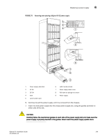
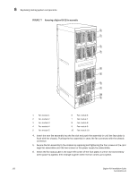
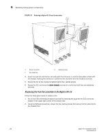
6 Replacing cooling system components FIGURE 77 Removing a BigIron RX-32 fan assembly 2 1 4 3 6 5 8 7 10 9 1 Fan module 1 2 Fan module 2 3 Fan module 3 4 Fan module 4 5 Fan module 5 6 Fan module 6 7 Fan module 7 8 Fan module 8 9 Fan module 9 10 Fan module 10 4. Insert the new fan assembly into the fan slot and push the assembly in until the face plate is flush with the chassis. Pushing the fan assembly in seats the fan connector with the chassis connector. 5. Secure the fan assembly to the chassis by replacing and tightening the four screws on the card cage fan assemblies and the two screws on the power supply fan assemblies. 6. Check the fan status LED in the lower left corner of the face plate. It will be red momentarily when power is applied, then change to green when the fan comes up to speed. 152 BigIron RX Installation Guide 53-1001811-01
-
 1
1 -
2
-
3
-
4
-
5
-
6
-
7
-
8
-
9
-
10
-
11
-
12
-
13
-
14
-
15
-
16
-
17
-
18
-
19
-
20
-
21
-
22
-
23
-
24
-
25
-
26
-
27
-
28
-
29
-
30
-
31
-
32
-
33
-
34
-
35
-
36
-
37
-
38
-
39
-
40
-
41
-
42
-
43
-
44
-
45
-
46
-
47
-
48
-
49
-
50
-
51
-
52
-
53
-
54
-
55
-
56
-
57
-
58
-
59
-
60
-
61
-
62
-
63
-
64
-
65
-
66
-
67
-
68
-
69
-
70
-
71
-
72
-
73
-
74
-
75
-
76
-
77
-
78
-
79
-
80
-
81
-
82
-
83
-
84
-
85
-
86
-
87
-
88
-
89
-
90
-
91
-
92
-
93
-
94
-
95
-
96
-
97
-
98
-
99
-
100
-
101
-
102
-
103
-
104
-
105
-
106
-
107
-
108
-
109
-
110
-
111
-
112
-
113
-
114
-
115
-
116
-
117
-
118
-
119
-
120
-
121
-
122
-
123
-
124
-
125
-
126
-
127
-
128
-
129
-
130
-
131
-
132
-
133
-
134
-
135
-
136
-
137
-
138
-
139
-
140
-
141
-
142
-
143
-
144
-
145
-
146
-
147
-
148
-
149
-
150
-
151
-
152
-
153
-
154
-
155
-
156
-
157
-
158
-
 159
159 -
 160
160 -
 161
161 -
 162
162 -
 163
163 -
 164
164 -
 165
165 -
 166
166 -
 167
167 -
 168
168 -
 169
169 -
170
-
171
-
172
-
173
-
174
-
175
-
176
-
177
-
178
-
179
-
180
-
181
-
182
-
183
-
184
-
185
-
186
-
187
-
188
-
189
-
190
-
191
-
192
-
193
-
194
-
195
-
196
-
197
-
198
-
199
-
200
-
201
-
202
-
203
-
204
-
205
-
206
-
207
-
208
-
209
-
210
-
211
-
212
-
213
-
214
-
215
-
216
-
217
-
218
-
219
-
220
-
221
-
222
-
223
-
224
-
225
-
226
-
227
-
228
-
229
-
230
-
231
-
232
-
233
-
234
-
235
-
236
-
237
-
238
-
239
-
240
 |
 |
