Dell PowerConnect B-RX8 Installation Guide - Page 95
Switch fabric module, Power supplies AC, Desired state, Meaning, Abnormal, state, Meaning or action
 |
View all Dell PowerConnect B-RX8 manuals
Add to My Manuals
Save this manual to your list of manuals |
Page 95 highlights
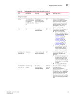
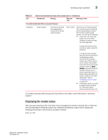
Verifying proper operation 2 TABLE 13 LED Desired and abnormal LED states after system power on (Continued) Desired state Meaning Abnormal state Meaning or action Link On Active On or blinking Switch fabric module A link is established Off with the remote port. The port is Off for an transmitting and extended receiving user packets. period. At this stage of the installation, you have not yet cabled the interface module ports, so this LED will be off. After cabling this port, if this LED is off, a link is not established with the remote port. For more information, refer to Table 16 on page 109. At this stage of the installation, you have not yet cabled the interface module ports, so this LED will be off. After cabling this port, if this LED is off, the port is not transmitting or receiving user packets. For information about action you can take to troubleshoot the problem, refer to Table 16 on page 109. Pwr On Active On Power supplies AC The module is Off receiving power. The switch fabric module is active and ready to switch user packets. Off for an extended period. The module is not receiving power. You can do the following: • If using AC power supplies, see the entry for the AC power supply LED in this table for more information. The switch fabric module is not active and user packets are not being switched from one interface module to another. You must replace the switch fabric module. For information about performing this task, refer to "Replacing a switch fabric module" on page 143. AC OK Green (steady) The power supply is Off receiving AC power from an AC power source. The power supply is not receiving power from an AC power source You can do the following: • Make sure that the power supply cord is connected securely to the wall outlet and the power supply. • Make sure that the wall outlet is rated for 115/120V and 20A. If it is not, obtain a cable that is compatibly rated for the outlet. • Make sure that the wall outlet has power. BigIron RX Installation Guide 83 53-1001811-01
-
 1
1 -
2
-
3
-
4
-
5
-
6
-
7
-
8
-
9
-
10
-
11
-
12
-
13
-
14
-
15
-
16
-
17
-
18
-
19
-
20
-
21
-
22
-
23
-
24
-
25
-
26
-
27
-
28
-
29
-
30
-
31
-
32
-
33
-
34
-
35
-
36
-
37
-
38
-
39
-
40
-
41
-
42
-
43
-
44
-
45
-
46
-
47
-
48
-
49
-
50
-
51
-
52
-
53
-
54
-
55
-
56
-
57
-
58
-
59
-
60
-
61
-
62
-
63
-
64
-
65
-
66
-
67
-
68
-
69
-
70
-
71
-
72
-
73
-
74
-
75
-
76
-
77
-
78
-
79
-
80
-
81
-
82
-
83
-
84
-
85
-
86
-
87
-
88
-
89
-
 90
90 -
 91
91 -
 92
92 -
 93
93 -
 94
94 -
 95
95 -
 96
96 -
 97
97 -
 98
98 -
 99
99 -
 100
100 -
101
-
102
-
103
-
104
-
105
-
106
-
107
-
108
-
109
-
110
-
111
-
112
-
113
-
114
-
115
-
116
-
117
-
118
-
119
-
120
-
121
-
122
-
123
-
124
-
125
-
126
-
127
-
128
-
129
-
130
-
131
-
132
-
133
-
134
-
135
-
136
-
137
-
138
-
139
-
140
-
141
-
142
-
143
-
144
-
145
-
146
-
147
-
148
-
149
-
150
-
151
-
152
-
153
-
154
-
155
-
156
-
157
-
158
-
159
-
160
-
161
-
162
-
163
-
164
-
165
-
166
-
167
-
168
-
169
-
170
-
171
-
172
-
173
-
174
-
175
-
176
-
177
-
178
-
179
-
180
-
181
-
182
-
183
-
184
-
185
-
186
-
187
-
188
-
189
-
190
-
191
-
192
-
193
-
194
-
195
-
196
-
197
-
198
-
199
-
200
-
201
-
202
-
203
-
204
-
205
-
206
-
207
-
208
-
209
-
210
-
211
-
212
-
213
-
214
-
215
-
216
-
217
-
218
-
219
-
220
-
221
-
222
-
223
-
224
-
225
-
226
-
227
-
228
-
229
-
230
-
231
-
232
-
233
-
234
-
235
-
236
-
237
-
238
-
239
-
240
 |
 |
