Dell PowerConnect B-RX8 Installation Guide - Page 79
BigIron RX-32 cable routing,
 |
View all Dell PowerConnect B-RX8 manuals
Add to My Manuals
Save this manual to your list of manuals |
Page 79 highlights
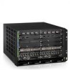
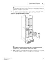
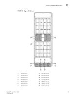
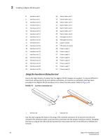
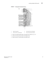
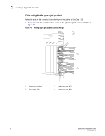
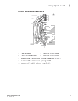
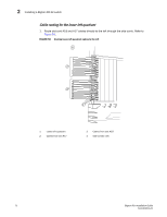
Installing a BigIron RX-32 switch 2 When using the tool to extract the boot or plug of a modular connector, cover the entire length of the boot or plug with the tool. Notice that one end of the tool has a "hook" side. Use this side to compress the locking tab while you remove the connector. BigIron RX-32 cable routing BigIron RX-32 cable management is designed to ensure access to the power supplies at the bottom of the chassis, and to keep the air inlet clear in the center of the chassis (this is essential for proper cooling). Cable management hardware at the top, bottom and sides of the chassis will assist you in channeling the cables in the proper direction. In general, cables from the outer interface modules are routed horizontally and away from the chassis. With the cable management upper cover swung open, cables from the remaining modules in the upper half of the chassis are routed up, then outwards along the channels. With the cable management lower cover swung open, the remaining modules in the lower half of the chassis follow a similar path downwards, above the power supplies. Figure 45 diagrams the cable routing, with the upper and lower covers removed for clarity. FIGURE 45 BigIron RX-32 cable routing diagram BigIron RX Installation Guide 67 53-1001811-01
-
 1
1 -
2
-
3
-
4
-
5
-
6
-
7
-
8
-
9
-
10
-
11
-
12
-
13
-
14
-
15
-
16
-
17
-
18
-
19
-
20
-
21
-
22
-
23
-
24
-
25
-
26
-
27
-
28
-
29
-
30
-
31
-
32
-
33
-
34
-
35
-
36
-
37
-
38
-
39
-
40
-
41
-
42
-
43
-
44
-
45
-
46
-
47
-
48
-
49
-
50
-
51
-
52
-
53
-
54
-
55
-
56
-
57
-
58
-
59
-
60
-
61
-
62
-
63
-
64
-
65
-
66
-
67
-
68
-
69
-
70
-
71
-
72
-
73
-
 74
74 -
 75
75 -
 76
76 -
 77
77 -
 78
78 -
 79
79 -
 80
80 -
 81
81 -
 82
82 -
 83
83 -
 84
84 -
85
-
86
-
87
-
88
-
89
-
90
-
91
-
92
-
93
-
94
-
95
-
96
-
97
-
98
-
99
-
100
-
101
-
102
-
103
-
104
-
105
-
106
-
107
-
108
-
109
-
110
-
111
-
112
-
113
-
114
-
115
-
116
-
117
-
118
-
119
-
120
-
121
-
122
-
123
-
124
-
125
-
126
-
127
-
128
-
129
-
130
-
131
-
132
-
133
-
134
-
135
-
136
-
137
-
138
-
139
-
140
-
141
-
142
-
143
-
144
-
145
-
146
-
147
-
148
-
149
-
150
-
151
-
152
-
153
-
154
-
155
-
156
-
157
-
158
-
159
-
160
-
161
-
162
-
163
-
164
-
165
-
166
-
167
-
168
-
169
-
170
-
171
-
172
-
173
-
174
-
175
-
176
-
177
-
178
-
179
-
180
-
181
-
182
-
183
-
184
-
185
-
186
-
187
-
188
-
189
-
190
-
191
-
192
-
193
-
194
-
195
-
196
-
197
-
198
-
199
-
200
-
201
-
202
-
203
-
204
-
205
-
206
-
207
-
208
-
209
-
210
-
211
-
212
-
213
-
214
-
215
-
216
-
217
-
218
-
219
-
220
-
221
-
222
-
223
-
224
-
225
-
226
-
227
-
228
-
229
-
230
-
231
-
232
-
233
-
234
-
235
-
236
-
237
-
238
-
239
-
240
 |
 |
