Dell PowerEdge 1300 Dell PowerEdge Systems Microprocessor Upgrade Guide - Page 10
Place the expansion cards in antistatic bags or on a grounded antistatic mat
 |
View all Dell PowerEdge 1300 manuals
Add to My Manuals
Save this manual to your list of manuals |
Page 10 highlights
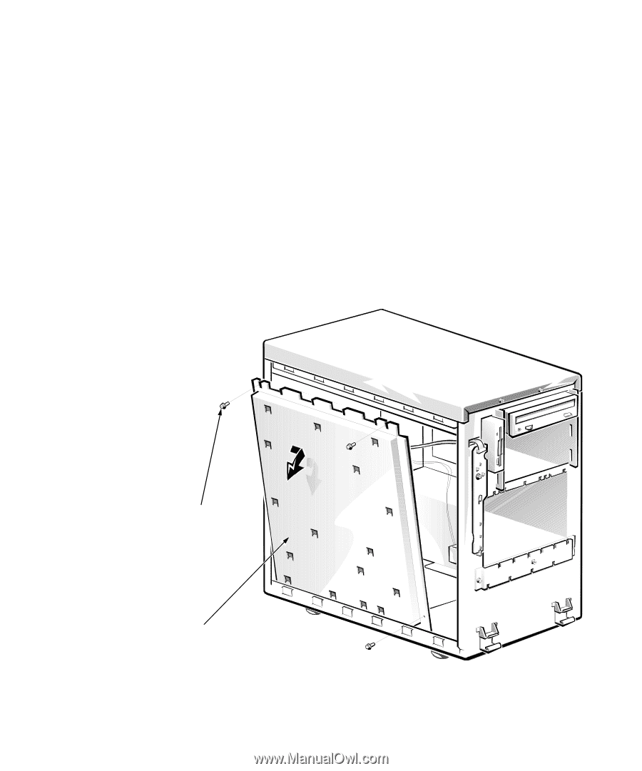
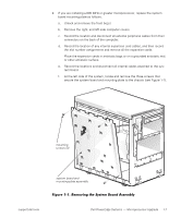
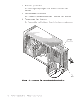
2. If you are installing a 600 MHz or greater microprocessor, replace the system board mounting plate as follows. a. Unlock and remove the front bezel. b. Remove the right- and left-side computer covers. c. Record the location and disconnect all external peripheral cables from their connectors on the back of the computer. d. Record the location of any internal expansion card cables, and then record the slot number assignments and remove all the expansion cards. Place the expansion cards in antistatic bags or on a grounded antistatic mat or other antistatic surface. e. Record the locations and disconnect all internal cables attached to the system board. f. At the left side of the system, locate and remove the three screws that secure the system board and mounting plate to the chassis (see Figure 1-1). mounting screws (3) system board and mounting-plate assembly support.dell.com Dell PowerEdge Systems - Microprocessor Upgrade 1-7
-
 1
1 -
2
-
3
-
4
-
 5
5 -
 6
6 -
 7
7 -
 8
8 -
 9
9 -
 10
10 -
 11
11 -
 12
12 -
 13
13 -
 14
14 -
 15
15 -
16
-
17
-
18
-
19
-
20
-
21
-
22
-
23
 |
 |