Dell PowerEdge 1300 Dell PowerEdge Systems Microprocessor Upgrade Guide - Page 12
Removing the Microprocessors, Lay the tray assembly with the system board facing up on a flat surface. - open
 |
View all Dell PowerEdge 1300 manuals
Add to My Manuals
Save this manual to your list of manuals |
Page 12 highlights
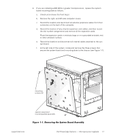
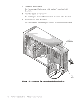
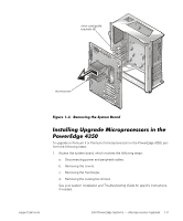
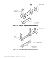
1. Remove the system board mounting tray as follows. a. Unlock and remove the computer cover. For instructions, see the Installation and Troubleshooting Guide. b. To access the system board, release the system-board tray latch at the back lower corner of the tray (see Figure 1-2) and pull the tray open to the first stop position (or service position). NOTE: From the service position, if you depress and release the tray latch and pull the tray out again, you will come to a second stop position that is used by manufacturing. To remove the tray completely from any position, depress and hold the latch, and pull the tray out of the chassis. c. Record the location of any internal expansion card cables, record the slot number assignments, and then remove all the expansion cards. Place the expansion cards in antistatic bags or on a grounded antistatic mat or other antistatic surface. d. Record the locations and disconnect all internal cables attached to the system board. e. Press and hold the tray release latch as you slide the system board and mounting tray assembly completely out of the chassis. f. Lay the tray assembly with the system board facing up on a flat surface. g. Remove the mounting screw from the mounting tray. h. Slide the system board 6.3 mm (0.25 inch) toward the front (left edge of the mounting tray, as shown in Figure 1-3) and lift the system board away from the mounting tray. 2. To install the upgrade mounting tray assembly (provided in your upgrade kit) in your PowerEdge 4300 system, perform the preceding steps in reverse order. 3. Remove the microprocessors. See "Removing the Microprocessors", found later in this document. support.dell.com Dell PowerEdge Systems - Microprocessor Upgrade 1-9
-
 1
1 -
2
-
3
-
4
-
5
-
6
-
 7
7 -
 8
8 -
 9
9 -
 10
10 -
 11
11 -
 12
12 -
 13
13 -
 14
14 -
 15
15 -
 16
16 -
 17
17 -
18
-
19
-
20
-
21
-
22
-
23
 |
 |