Dell PowerEdge 1300 Dell PowerEdge Systems Microprocessor Upgrade Guide - Page 15
Removing the Microprocessors, Installing the Upgrade Microprocessor
 |
View all Dell PowerEdge 1300 manuals
Add to My Manuals
Save this manual to your list of manuals |
Page 15 highlights
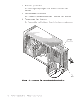
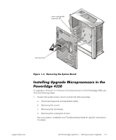
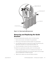
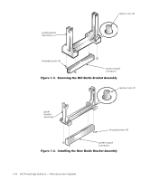
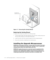
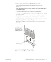
2. Remove the microprocessors. See "Removing the Microprocessors", found later in this document. 3. Remove and replace the guide brackets. See "Removing and Replacing the Guide Brackets", found later in this document. 4. Install the upgrade microprocessor. See "Installing the Upgrade Microprocessor", found later in this document. 5. Reassemble and check the system. See "Reassembling and Checking the System", found later in this document. To remove the current microprocessors from the system board, perform the following steps. 1. Unscrew and remove the two large thumbscrew retention pins that secure the microprocessor to the system board. 2. Press the microprocessor's release latches inward until they snap into position (see Figure 1-4). NOTE: Figure 1-4 illustrates the SEC cartridge. The heat sink on the single-edge connector cartridge 2 (SECC2) package is different. 3. Grasp the microprocessor assembly firmly and pull it away from the microprocessor guide bracket assembly. You must use up to 15 pounds (lb) of force to disengage the microprocessor from the connector. 1-12 Dell PowerEdge Systems - Microprocessor Upgrade
-
 1
1 -
2
-
3
-
4
-
5
-
6
-
7
-
8
-
9
-
 10
10 -
 11
11 -
 12
12 -
 13
13 -
 14
14 -
 15
15 -
 16
16 -
 17
17 -
 18
18 -
 19
19 -
 20
20 -
21
-
22
-
23
 |
 |