Dell PowerEdge 1655MC Replacing the Server Module Board - Page 17
Connecting the Hard-Drive Module to the Server Module Board
 |
View all Dell PowerEdge 1655MC manuals
Add to My Manuals
Save this manual to your list of manuals |
Page 17 highlights
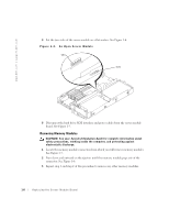
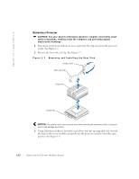
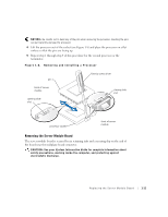
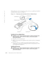
1 Ensure that the processor socket is in the fully open position. See Figure 1-8. NOTICE: Positioning the processor incorrectly can permanently damage the processor and the server module when you turn on the server module. When placing the processor in the socket, be sure that all of the pins on the processor go into the corresponding holes. Be careful not to bend the pins. 2 Align pin 1 on the processor with pin 1 on the processor socket. See Figure 1-8. NOTE: Force is not needed to install the processor in the socket. When the processor is aligned correctly, it should drop into the socket. 3 Install the processor in the socket. See Figure 1-8. If the original processor or terminator pins were bent or damaged, use the spare processor or terminator from the parts kit. NOTICE: Be careful not to use excessive force while closing the processor socket. Excessive force could damage the socket. 4 Using a flat-tip screwdriver, insert the screwdriver into the closing slide slot (toward the front of the server module) and gently pry the processor socket to the fully closed position. 5 Place the heat sink on the processor. 6 Orient the heat-sink clip as shown in Figure 1-7. 7 Hook the heat-sink clip over the processor socket tab that is toward the front of the server module. 8 Push down on and pivot the heat-sink release lever until it latches onto the processor socket tab. 9 Repeat step 1 through step 8 for a second processor or step 1 through step 4 for a terminator. Connecting the Hard-Drive Module to the Server Module Board CAUTION: See your System Information Guide for complete information about safety precautions, working inside the computer, and protecting against electrostatic discharge. 1 Place the two sides of the server module on a flat surface as shown in Figure 1-4. 2 Ensure that the SCSI interface cable is not damaged. If the cable is damaged, use the spare SCSI interface cable from the parts kit. Replacing the Ser ver Module Board 1-13
-
 1
1 -
2
-
3
-
4
-
5
-
6
-
7
-
8
-
9
-
10
-
11
-
 12
12 -
 13
13 -
 14
14 -
 15
15 -
 16
16 -
 17
17 -
 18
18 -
 19
19 -
 20
20 -
 21
21 -
 22
22 -
23
-
24
 |
 |