Dell PowerEdge 1655MC Replacing the Server Module Board - Page 18
Installing Memory Modules, Closing the Server Module
 |
View all Dell PowerEdge 1655MC manuals
Add to My Manuals
Save this manual to your list of manuals |
Page 18 highlights
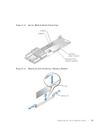
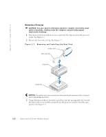
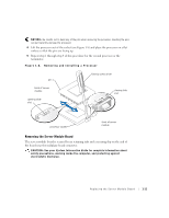
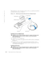
www.dell.com | support.dell.com 3 Ensure that the power cable is not damaged. If the cable is damaged, use the spare power cable from the parts kit. 4 Connect the hard drive SCSI interface and power cables to the server module board. See Figure 1-5. Installing Memory Modules CAUTION: See your System Information Guide for complete information about safety precautions, working inside the computer, and protecting against electrostatic discharge. 1 Locate the memory module connectors in which you will install a memory module. See Figure 1-5. 2 Press down and outward on the ejectors, as shown in Figure 1-6, to allow the memory module to be inserted into the connector. 3 Align the notch in the memory module's edge connector with the alignment key in the socket, and insert the memory module in the connector. See Figure 1-6. The memory module connector has an alignment key that allows the memory module to be installed in the connector in only one way. 4 Press down on the memory module with your thumbs while pulling up on the ejectors with your index fingers to lock the memory module into the connector. See Figure 1-6. When the memory module is properly seated in the connector, the ejectors should align with the ejectors on the other connectors with memory modules installed. 5 Repeat step 1 through step 4 of this procedure to install the remaining memory module. Closing the Server Module CAUTION: See your System Information Guide for complete information about safety precautions, working inside the computer, and protecting against electrostatic discharge. 1 Insert the tabs on the left side of the server module into the slots on the right side of the server module and rotate the sides up. See Figure 1-3 and Figure 1-4. 2 Slide the left side of the server module forward approximately 12.7 mm (0.5 inch). See Figure 1-3. 3 Using a #2 Phillips screwdriver, tighten the two captive screws that secure the front panel to the server module. See Figure 1-3. 1-14 Replacing the Server Module Board
-
 1
1 -
2
-
3
-
4
-
5
-
6
-
7
-
8
-
9
-
10
-
11
-
12
-
 13
13 -
 14
14 -
 15
15 -
 16
16 -
 17
17 -
 18
18 -
 19
19 -
 20
20 -
 21
21 -
 22
22 -
 23
23 -
24
 |
 |