Dell PowerEdge 2550 Rack Installation Guide - Page 26
Installing the Cable Management Arm
 |
View all Dell PowerEdge 2550 manuals
Add to My Manuals
Save this manual to your list of manuals |
Page 26 highlights
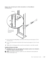
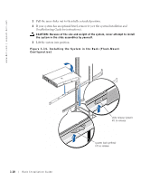
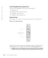
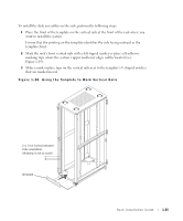
www.dell.com | support.dell.com Installing the Cable Management Arm 1 Facing the back of the two-post rack, locate the two slots and the threaded hole on the back right side of the system. 2 Insert the bracket on the end of the cable management arm to the mating slots and threaded hole, and secure the arm using the captive thumbscrew. Figure 1-16. Installing the Cable Management Arm quick-disconnect knobs captive thumbscrew 3 Align the free end of the cable-management arm (the end with the half-hinge) to the hinge-half mate on the back-right side (as viewed from the back) of the system (see Figure 1-16). 4 Squeeze the quick-disconnect knobs on the free end of the cable-management arm and align the two hinge halves to attach the arm to the bracket on the back of the system chassis (see Figure 1-16). 5 Attach the input/output (I/O) cables to their respective expansion cards on the back of the system. 1-20 Rack Installation Guide
-
 1
1 -
2
-
3
-
4
-
5
-
6
-
7
-
8
-
9
-
10
-
11
-
12
-
13
-
14
-
15
-
16
-
17
-
18
-
19
-
20
-
 21
21 -
 22
22 -
 23
23 -
 24
24 -
 25
25 -
 26
26 -
 27
27 -
 28
28 -
 29
29 -
 30
30 -
 31
31 -
32
-
33
-
34
-
35
-
36
-
37
-
38
-
39
-
40
 |
 |
