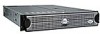
Dell PowerEdge 2550 Rack Installation Guide - Page 6
Installing the Support Tray in a Rack, Installing the Slide Assemblies - rails
 |
View all Dell PowerEdge 2550 manuals
Add to My Manuals
Save this manual to your list of manuals |
Page 6 highlights
Figure 1-6. Figure 1-7. Figure 1-8. Figure 1-9. Figure 1-10. Figure 1-11. Figure 1-12. Figure 1-13. Figure 1-14. Figure 1-15. Figure 1-16. Figure 1-17. Figure 1-18. Figure 1-19. Figure 1-20. Figure 1-21. Figure 1-22. Figure 1-23. Figure 1-24. Installing the Center-Mount Brackets to the Support Tray 1-8 Installing the Support Tray in a Rack With Universal-Hole Spacing 1-9 Installing the Support Tray in a Rack With Wide-Hole Spacing 1-10 Securing the System in the Rack (Flush-Mounted Tray Shown on Universal-Hole Spacing Rack 1-11 Two-Post RapidRails Rack Kit Components 1-12 Installing the Slide Assemblies for Center-Mount Configuration 1-15 Positioning Brackets for Flush-Mount Installation 1-16 Installing the Slide Assemblies for Flush-Mount Configuration 1-17 Installing the System in the Rack (Flush-Mount Configuration 1-18 Securing the System in the Rack (Flush-Mount Configuration 1-19 Installing the Cable Management Arm . . . 1-20 Attaching the Strain Relief Bracket . . . . 1-21 Four-Post RapidRails Rack Kit Contents . . 1-23 One Rack Unit 1-24 Using the Template to Mark Vertical Rails 1-25 Installing the Slide Assemblies 1-27 Installing the System in the Rack . . . . . 1-29 Installing the Cable Management Arm . . . 1-30 Attaching the Strain Relief Bracket . . . . 1-31 6 Contents
-
 1
1 -
 2
2 -
 3
3 -
 4
4 -
 5
5 -
 6
6 -
 7
7 -
 8
8 -
 9
9 -
 10
10 -
 11
11 -
 12
12 -
13
-
14
-
15
-
16
-
17
-
18
-
19
-
20
-
21
-
22
-
23
-
24
-
25
-
26
-
27
-
28
-
29
-
30
-
31
-
32
-
33
-
34
-
35
-
36
-
37
-
38
-
39
-
40
 |
 |
