Dell PowerEdge M820 Dell PowerEdge M820 Systems Owner's Manual - Page 30
Installing The Cooling Shroud, Hard Drives/SSDs
 |
View all Dell PowerEdge M820 manuals
Add to My Manuals
Save this manual to your list of manuals |
Page 30 highlights
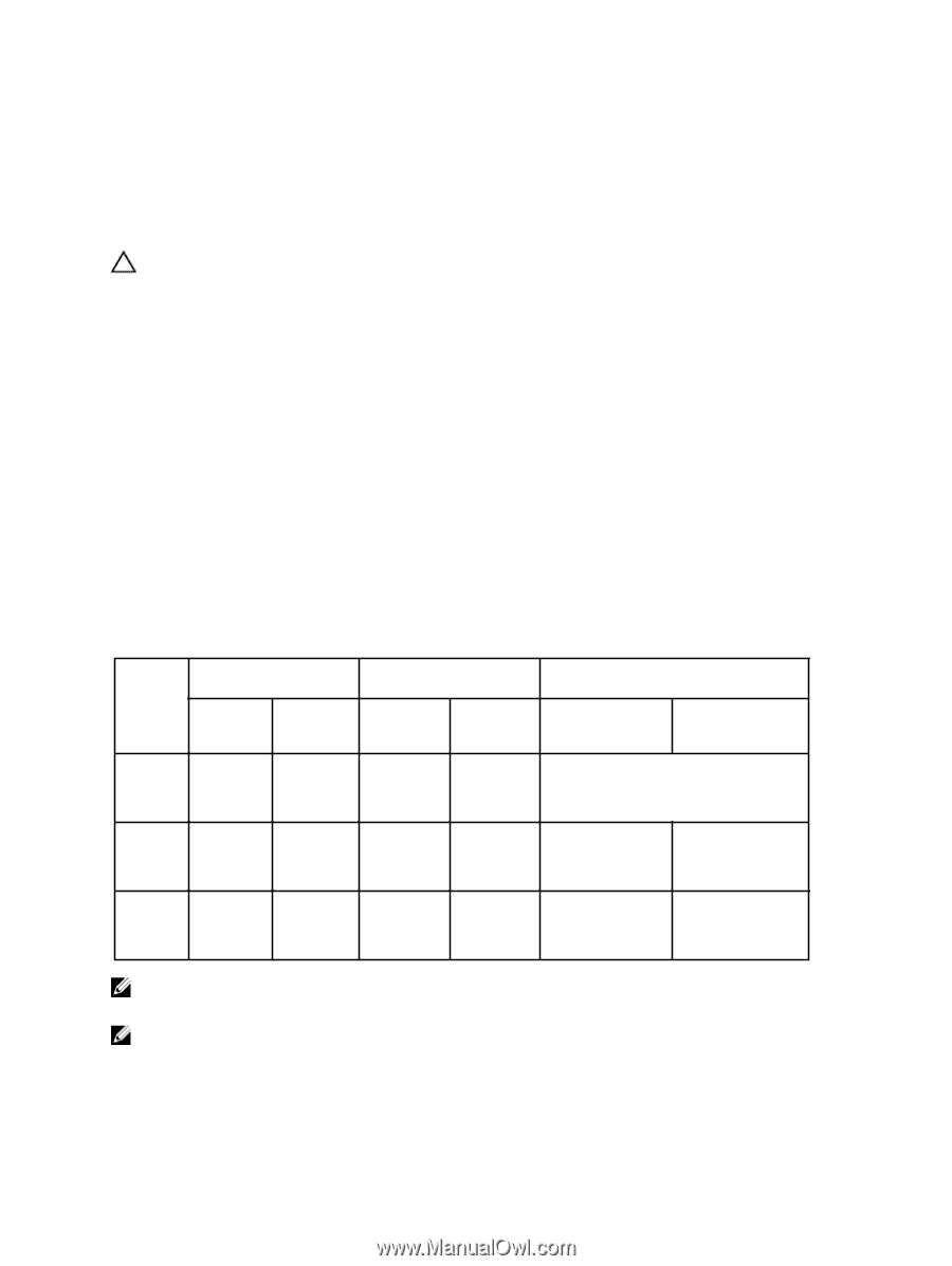
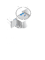
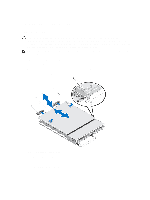
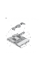
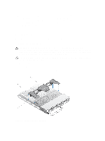
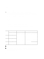
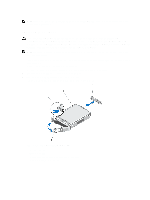
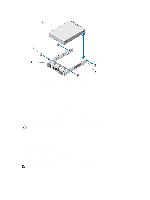
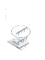
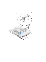
1. tabs (4) 2. cooling shroud 3. slots on the chassis (4) Installing The Cooling Shroud CAUTION: Many repairs may only be done by a certified service technician. You should only perform troubleshooting and simple repairs as authorized in your product documentation, or as directed by the online or telephone service and support team. Damage due to servicing that is not authorized by Dell is not covered by your warranty. Read and follow the safety instructions that came with the product. 1. Align the tabs on the cooling shroud with the slots on the chassis. 2. Lower the cooling shroud into the system until the tabs seat securely on the slots on the blade chassis. 3. Close the blade. 4. Install the blade in the enclosure. Hard Drives/SSDs • The system supports up to four 2.5 inch SAS hard drives or two PCIe SSDs. • All drives connect to the system board through the SSD/SAS hard-drive backplane. • Hard drives/PCIe SSDs are supplied in special hot-swappable drive carriers that fit in the drive slots. • All empty drive slots must have hard-drive blanks installed. The following table lists the supported hard drive/SSD configurations. Table 1. Supported Hard-Drive/Controller Card/Drive Backplane Configurations Number of Drives Drive Population Drive Bay 0 Drive Bay 1 Four Two SAS Two SAS hard drives hard drives Storage Controller Card Type Installed Drive Backplane Installed MiniPERC CARD Connector PCIe EXTENDER Connector System Board Backplane Connector J_BP0 System Board Backplane Connector J_BP1 Storage controller card SAS drive backplane with four drive slots Four Two SAS Two PCIe Storage hard drives SSDs controller card PCIe extender card SAS hard-drive backplane with two drive slots PCIe SSD backplane with two drive slots Two Two SAS - Storage - SAS hard-drive - hard drives controller backplane with two card drive slots NOTE: The SAS drive backplane with four drive slots is installed on the system board connectors labeled J_BP0 and J_BP1. NOTE: SAS hard-drive backplane (with two drive slots) for drives installed in drive bay 0 is installed on the system board connector labeled J_BP0. The PCIe SSD backplane (with two drive slots) for PCIe SSDs is installed on the system board connector labeled J_BP1. 30
-
 1
1 -
2
-
3
-
4
-
5
-
6
-
7
-
8
-
9
-
10
-
11
-
12
-
13
-
14
-
15
-
16
-
17
-
18
-
19
-
20
-
21
-
22
-
23
-
24
-
 25
25 -
 26
26 -
 27
27 -
 28
28 -
 29
29 -
 30
30 -
 31
31 -
 32
32 -
 33
33 -
 34
34 -
 35
35 -
36
-
37
-
38
-
39
-
40
-
41
-
42
-
43
-
44
-
45
-
46
-
47
-
48
-
49
-
50
-
51
-
52
-
53
-
54
-
55
-
56
-
57
-
58
-
59
-
60
-
61
-
62
-
63
-
64
-
65
-
66
-
67
-
68
-
69
-
70
-
71
-
72
-
73
-
74
-
75
-
76
-
77
-
78
-
79
-
80
-
81
-
82
-
83
-
84
-
85
-
86
-
87
-
88
-
89
-
90
-
91
-
92
-
93
-
94
-
95
-
96
-
97
-
98
-
99
-
100
-
101
-
102
-
103
-
104
-
105
-
106
-
107
-
108
-
109
-
110
-
111
-
112
-
113
-
114
-
115
-
116
-
117
-
118
-
119
-
120
-
121
-
122
-
123
-
124
-
125
-
126
-
127
-
128
-
129
-
130
-
131
-
132
-
133
-
134
-
135
-
136
-
137
-
138
-
139
 |
 |