Dell PowerEdge M820 Dell PowerEdge M820 Systems Owner's Manual - Page 50
Installing The System Board, Removing and Installing the System Board
 |
View all Dell PowerEdge M820 manuals
Add to My Manuals
Save this manual to your list of manuals |
Page 50 highlights
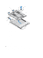
Figure 20. Removing and Installing the System Board 1. I/O connector cover 2. retention pin 3. system board 4. tabs on system chassis 5. slots in system board tray Installing The System Board 1. Transfer the following components to the new system board: - storage controller card(s) - internal USB key - processors and heat sinks, or processor/DIMM blanks - memory modules and memory module blanks CAUTION: Ensure that the system board plate is parallel with the chassis. 2. Slide the new system board into the open end of the blade chassis until the retention latch engages. When the board assembly is installed correctly, the tabs on the system board pan snap into the corresponding openings in the floor of the blade chassis. 50
-
 1
1 -
2
-
3
-
4
-
5
-
6
-
7
-
8
-
9
-
10
-
11
-
12
-
13
-
14
-
15
-
16
-
17
-
18
-
19
-
20
-
21
-
22
-
23
-
24
-
25
-
26
-
27
-
28
-
29
-
30
-
31
-
32
-
33
-
34
-
35
-
36
-
37
-
38
-
39
-
40
-
41
-
42
-
43
-
44
-
 45
45 -
 46
46 -
 47
47 -
 48
48 -
 49
49 -
 50
50 -
 51
51 -
 52
52 -
 53
53 -
 54
54 -
 55
55 -
56
-
57
-
58
-
59
-
60
-
61
-
62
-
63
-
64
-
65
-
66
-
67
-
68
-
69
-
70
-
71
-
72
-
73
-
74
-
75
-
76
-
77
-
78
-
79
-
80
-
81
-
82
-
83
-
84
-
85
-
86
-
87
-
88
-
89
-
90
-
91
-
92
-
93
-
94
-
95
-
96
-
97
-
98
-
99
-
100
-
101
-
102
-
103
-
104
-
105
-
106
-
107
-
108
-
109
-
110
-
111
-
112
-
113
-
114
-
115
-
116
-
117
-
118
-
119
-
120
-
121
-
122
-
123
-
124
-
125
-
126
-
127
-
128
-
129
-
130
-
131
-
132
-
133
-
134
-
135
-
136
-
137
-
138
-
139
 |
 |
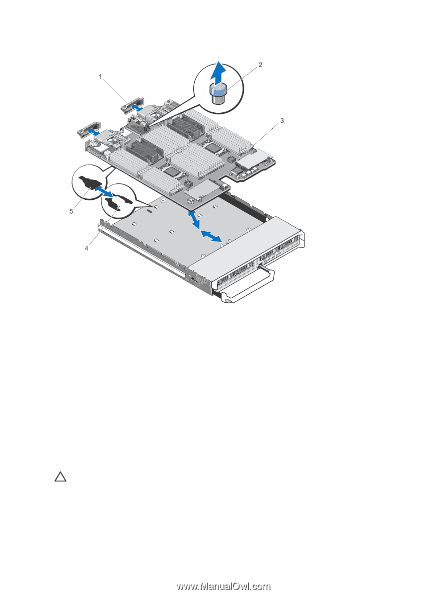
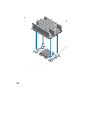
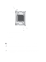
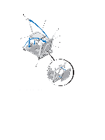
Figure 20. Removing and Installing the System Board
1. I/O connector cover
2. retention pin
3. system board
4. tabs on system chassis
5. slots in system board tray
Installing The System Board
1.
Transfer the following components to the new system board:
–
storage controller card(s)
–
internal USB key
–
processors and heat sinks, or processor/DIMM blanks
–
memory modules and memory module blanks
CAUTION: Ensure that the system board plate is parallel with the chassis.
2.
Slide the new system board into the open end of the blade chassis until the retention latch engages.
When the board assembly is installed correctly, the tabs on the system board pan snap into the corresponding
openings in the floor of the blade chassis.
50