Dell PowerEdge M820 Dell PowerEdge M820 Systems Owner's Manual - Page 55
Memory Mirroring, Sample Memory Configurations
 |
View all Dell PowerEdge M820 manuals
Add to My Manuals
Save this manual to your list of manuals |
Page 55 highlights
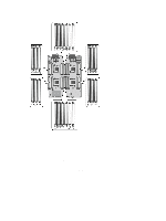
NOTE: Memory sparing does not offer protection against a multi-bit uncorrectable error. NOTE: Both Advanced ECC/Lockstep and Optimizer modes support Memory Sparing. Memory Mirroring Memory Mirroring offers the strongest DIMM reliability mode compared to all other modes, providing improved uncorrectable multi-bit failure protection. In a mirrored configuration, the total available system memory is one half of the total installed physical memory. Half of the installed memory is used to mirror the active DIMMs. In the event of an uncorrectable error, the system will switch over to the mirrored copy. This ensures SDDC and multi-bit protection. Memory installation guidelines: • Memory modules must be identical in size, speed, and technology. • DIMMs installed in memory sockets with white release tabs must be identical and similar rule applies for sockets with black and green release tabs. This ensures that identical DIMMs are installed in matched pairs for example, A1 with A2, A3 with A4, A5 with A6, and so on. Sample Memory Configurations The following tables show sample memory configurations that follow the appropriate memory guidelines stated in this section. NOTE: 1R, 2R, and 4R in the following tables indicate single-, dual-, and quad-rank DIMMs. Table 3. Memory Configurations - Two Processors System Capacity (in GB) 4 DIMM Size (in GB) 2 Number of DIMMs 2 8 2 4 16 2 8 20 2 10 32 2 16 32 4 8 64 4 16 64 8 8 96 4 24 Organization and Speed 1R x8, 1333 MT/s 1R x8, 1600 MT/s 1R x8, 1333 MT/s 1R x8, 1600 MT/s 1R x8, 1333 MT/s 1R x8, 1600 MT/s 1R x8, 1333 MT/s 1R x8, 1600 MT/s 1R x8, 1333 MT/s 1R x8, 1600 MT/s 2R x8, 1333 MT/s 2R x8, 1600 MT/s 2R x8, 1333 MT/s 2R x4, 1333 MT/s 2R x4, 1600 MT/s 2R x8, 1333 MT/s DIMM Slot Population A1, B1 A1, A2, B1, B2 A1, A2, A3, A4, B1, B2, B3, B4 A1, A2, A3, A4, A5, B1, B2, B3, B4, B5 A1, A2, A3, A4, A5, A6, A7, A8, B1, B2, B3, B4, B5, B6, B7, B8 A1, A2, A3, A4, B1, B2, B3, B4 A1, A2, A3, A4, A5, A6, A7, A8, B1, B2, B3, B4, B5, B6, B7, B8 A1, A2, A3, A4, B1, B2, B3, B4 A1, A2, A3, A4, A5, A6, A7, A8, A9, A10, A11, A12, B1, B2, B3, B4, B5, B6, B7, B8, B9, B10, B11, B12 55
-
 1
1 -
2
-
3
-
4
-
5
-
6
-
7
-
8
-
9
-
10
-
11
-
12
-
13
-
14
-
15
-
16
-
17
-
18
-
19
-
20
-
21
-
22
-
23
-
24
-
25
-
26
-
27
-
28
-
29
-
30
-
31
-
32
-
33
-
34
-
35
-
36
-
37
-
38
-
39
-
40
-
41
-
42
-
43
-
44
-
45
-
46
-
47
-
48
-
49
-
 50
50 -
 51
51 -
 52
52 -
 53
53 -
 54
54 -
 55
55 -
 56
56 -
 57
57 -
 58
58 -
 59
59 -
 60
60 -
61
-
62
-
63
-
64
-
65
-
66
-
67
-
68
-
69
-
70
-
71
-
72
-
73
-
74
-
75
-
76
-
77
-
78
-
79
-
80
-
81
-
82
-
83
-
84
-
85
-
86
-
87
-
88
-
89
-
90
-
91
-
92
-
93
-
94
-
95
-
96
-
97
-
98
-
99
-
100
-
101
-
102
-
103
-
104
-
105
-
106
-
107
-
108
-
109
-
110
-
111
-
112
-
113
-
114
-
115
-
116
-
117
-
118
-
119
-
120
-
121
-
122
-
123
-
124
-
125
-
126
-
127
-
128
-
129
-
130
-
131
-
132
-
133
-
134
-
135
-
136
-
137
-
138
-
139
 |
 |