Dell PowerEdge M820 Dell PowerEdge M820 Systems Owner's Manual - Page 49
System Board, Removing The System Board
 |
View all Dell PowerEdge M820 manuals
Add to My Manuals
Save this manual to your list of manuals |
Page 49 highlights
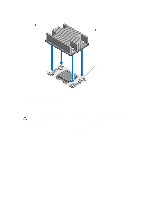
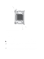
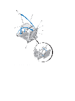
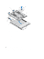
As the system boots, it detects the presence of the new processor and automatically changes the system configuration information in the System Setup. 10. Press to enter the System Setup and check that the processor information matches the new system configuration. 11. Run the system diagnostics to verify that the new processor operates correctly. 12. Update the system BIOS. System Board Removing The System Board CAUTION: Many repairs may only be done by a certified service technician. You should only perform troubleshooting and simple repairs as authorized in your product documentation, or as directed by the online or telephone service and support team. Damage due to servicing that is not authorized by Dell is not covered by your warranty. Read and follow the safety instructions that came with the product. 1. Remove the blade from the enclosure. 2. Open the blade. 3. Install an I/O connector cover on the I/O connector(s) at the back of the board. WARNING: The processor and heat sink can become extremely hot. Be sure the processor has had sufficient time to cool before handling. WARNING: The memory modules are hot to the touch for some time after the system has been powered down. Allow time for the memory modules to cool before handling them. Handle the memory modules by the card edges and avoid touching the components. NOTE: If you are removing more than one hard drive/SSD, label them so you can replace them in their original locations. 4. Remove the following components: a) hard drives/SSDs b) hard-drive backplane(s) c) cooling shroud d) mezzanine cards CAUTION: Do not lift the system board assembly by grasping a memory module, processor, or other components. 5. Hold the blade chassis with one hand, lift and pull the system board retention pin with the other hand, and then slide the system board out of the open end of the chassis. 6. Ensure that the I/O connector cover is still in place on the I/O connector at the back of the board. 7. Remove the memory modules and memory module blanks. 8. Remove the processor(s). 9. Remove the storage controller(s). 49
-
 1
1 -
2
-
3
-
4
-
5
-
6
-
7
-
8
-
9
-
10
-
11
-
12
-
13
-
14
-
15
-
16
-
17
-
18
-
19
-
20
-
21
-
22
-
23
-
24
-
25
-
26
-
27
-
28
-
29
-
30
-
31
-
32
-
33
-
34
-
35
-
36
-
37
-
38
-
39
-
40
-
41
-
42
-
43
-
 44
44 -
 45
45 -
 46
46 -
 47
47 -
 48
48 -
 49
49 -
 50
50 -
 51
51 -
 52
52 -
 53
53 -
 54
54 -
55
-
56
-
57
-
58
-
59
-
60
-
61
-
62
-
63
-
64
-
65
-
66
-
67
-
68
-
69
-
70
-
71
-
72
-
73
-
74
-
75
-
76
-
77
-
78
-
79
-
80
-
81
-
82
-
83
-
84
-
85
-
86
-
87
-
88
-
89
-
90
-
91
-
92
-
93
-
94
-
95
-
96
-
97
-
98
-
99
-
100
-
101
-
102
-
103
-
104
-
105
-
106
-
107
-
108
-
109
-
110
-
111
-
112
-
113
-
114
-
115
-
116
-
117
-
118
-
119
-
120
-
121
-
122
-
123
-
124
-
125
-
126
-
127
-
128
-
129
-
130
-
131
-
132
-
133
-
134
-
135
-
136
-
137
-
138
-
139
 |
 |