Dell PowerEdge M820 Dell PowerEdge M820 Systems Owner's Manual - Page 51
System Memory, System profile selected for example, Performance Optimized, Custom
 |
View all Dell PowerEdge M820 manuals
Add to My Manuals
Save this manual to your list of manuals |
Page 51 highlights
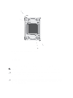
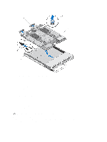
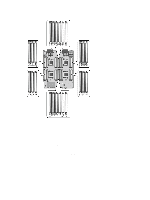
3. Replace the mezzanine cards in their original locations. 4. Reinstall the hard-drive backplane(s). 5. Replace the hard drives/SSDs. Ensure that you reinstall the hard drives/SSDs in their original locations. 6. Reinstall the cooling shroud. 7. Install the SD card(s). 8. Close the blade. 9. Remove the plastic I/O connector covers from the back of the blade. 10. Install the blade in the enclosure. 11. Import your new or existing iDRAC Enterprise license. For more information, see the iDRAC7 User's Guide, at support.dell.com/manuals. System Memory Your system supports DDR3 registered DIMMs (RDIMMs) and load reduced DIMMs (LRDIMMs). It supports DDR3 and DDR3L voltage specifications. NOTE: MT/s indicates DIMM speed in MegaTransfers per second. Memory bus operating frequency can be either 800 MT/s, 1066 MT/s , 1333 MT/s, or 1600 MT/s depending on the: • DIMM type (RDIMM or LRDIMM) • DIMM configuration (number of ranks) • Maximum frequency of the DIMMs • Number of DIMMs populated per channel • DIMM operating voltage • System profile selected (for example, Performance Optimized, Custom, or Dense Configuration Optimized) • Maximum supported DIMM frequency of the processors The system contains 48 memory sockets split into four sets of 12 sockets, one set per processor. Each 12-socket set is organized into four channels. In each channel, the release levers of the first socket are marked white, the second socket black, and the third socket green. NOTE: DIMMs in sockets A1 to A12 are assigned to processor 1, B1 to B12 to processor 2, C1 to C12 to processor 3, and D1 to D12 to processor 4. 51
-
 1
1 -
2
-
3
-
4
-
5
-
6
-
7
-
8
-
9
-
10
-
11
-
12
-
13
-
14
-
15
-
16
-
17
-
18
-
19
-
20
-
21
-
22
-
23
-
24
-
25
-
26
-
27
-
28
-
29
-
30
-
31
-
32
-
33
-
34
-
35
-
36
-
37
-
38
-
39
-
40
-
41
-
42
-
43
-
44
-
45
-
 46
46 -
 47
47 -
 48
48 -
 49
49 -
 50
50 -
 51
51 -
 52
52 -
 53
53 -
 54
54 -
 55
55 -
 56
56 -
57
-
58
-
59
-
60
-
61
-
62
-
63
-
64
-
65
-
66
-
67
-
68
-
69
-
70
-
71
-
72
-
73
-
74
-
75
-
76
-
77
-
78
-
79
-
80
-
81
-
82
-
83
-
84
-
85
-
86
-
87
-
88
-
89
-
90
-
91
-
92
-
93
-
94
-
95
-
96
-
97
-
98
-
99
-
100
-
101
-
102
-
103
-
104
-
105
-
106
-
107
-
108
-
109
-
110
-
111
-
112
-
113
-
114
-
115
-
116
-
117
-
118
-
119
-
120
-
121
-
122
-
123
-
124
-
125
-
126
-
127
-
128
-
129
-
130
-
131
-
132
-
133
-
134
-
135
-
136
-
137
-
138
-
139
 |
 |