Dell PowerEdge M820 Dell PowerEdge M820 Systems Owner's Manual - Page 7
About Your System, Front-Panel Features And Indicators, Using USB Diskette or USB DVD/CD Drives
 |
View all Dell PowerEdge M820 manuals
Add to My Manuals
Save this manual to your list of manuals |
Page 7 highlights
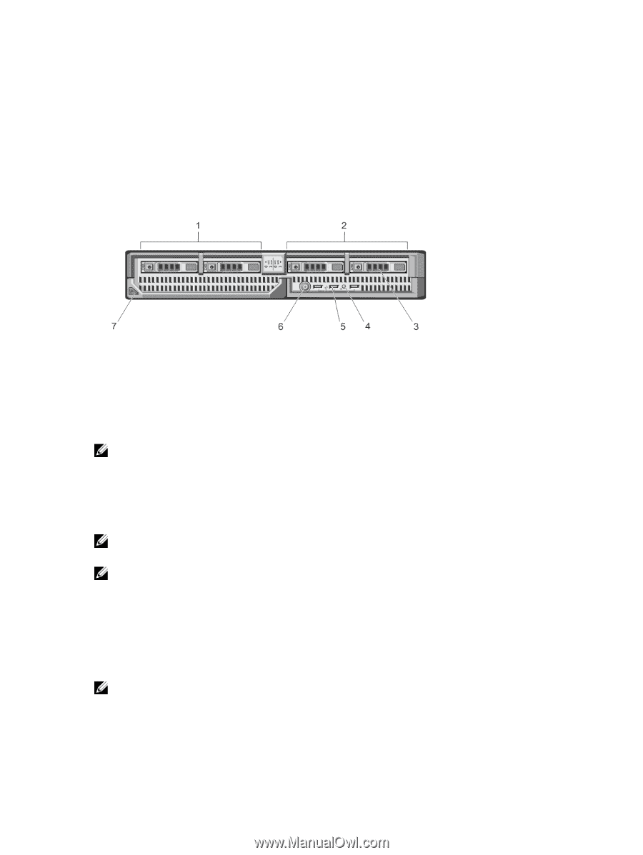
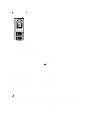
1 About Your System Front-Panel Features And Indicators Figure 1. Front-Panel Features and Indicators 1. drive bay 0 2. drive bay 1 3. SAS hard drives/PCIe SSDs 4. status/identification indicator 5. USB connectors (3) 6. blade power button 7. blade handle release button NOTE: For more information on supported hard-drive/PCIe SSD configurations, see Hard Drives/SSDs. Using USB Diskette or USB DVD/CD Drives The blade has USB ports on the front which allow you to connect a USB diskette drive, USB flash drive, USB DVD/CD drive, keyboard, or mouse. The USB drives can be used to configure the blade. NOTE: Your blade supports only Dell-branded USB 2.0 drives. Use the optional external drive storage tray to support the drive while in use. NOTE: If the drive must be designated as the boot drive, connect the USB drive, restart the system, then enter the System Setup and set the drive as first in the boot sequence. The USB device is displayed in the boot order setup screen only if it is attached to the system before you run the System Setup. You can also select the boot device by pressing during system start-up and selecting a boot device for the current boot sequence. Hard-Drive/SSD Indicator Patterns The hard-drive/SSD indicators display different patterns as drive events occur in the system. NOTE: The blade must have a hard drive/SSD or a hard-drive blank installed in each drive bay. 7
-
 1
1 -
 2
2 -
 3
3 -
 4
4 -
 5
5 -
 6
6 -
 7
7 -
 8
8 -
 9
9 -
 10
10 -
 11
11 -
 12
12 -
13
-
14
-
15
-
16
-
17
-
18
-
19
-
20
-
21
-
22
-
23
-
24
-
25
-
26
-
27
-
28
-
29
-
30
-
31
-
32
-
33
-
34
-
35
-
36
-
37
-
38
-
39
-
40
-
41
-
42
-
43
-
44
-
45
-
46
-
47
-
48
-
49
-
50
-
51
-
52
-
53
-
54
-
55
-
56
-
57
-
58
-
59
-
60
-
61
-
62
-
63
-
64
-
65
-
66
-
67
-
68
-
69
-
70
-
71
-
72
-
73
-
74
-
75
-
76
-
77
-
78
-
79
-
80
-
81
-
82
-
83
-
84
-
85
-
86
-
87
-
88
-
89
-
90
-
91
-
92
-
93
-
94
-
95
-
96
-
97
-
98
-
99
-
100
-
101
-
102
-
103
-
104
-
105
-
106
-
107
-
108
-
109
-
110
-
111
-
112
-
113
-
114
-
115
-
116
-
117
-
118
-
119
-
120
-
121
-
122
-
123
-
124
-
125
-
126
-
127
-
128
-
129
-
130
-
131
-
132
-
133
-
134
-
135
-
136
-
137
-
138
-
139
 |
 |