Dell PowerEdge R900 Hardware Owner's Manual (PDF) - Page 106
ZIF socket. See Removing a Processor Filler Blank
 |
View all Dell PowerEdge R900 manuals
Add to My Manuals
Save this manual to your list of manuals |
Page 106 highlights
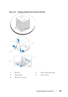
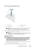
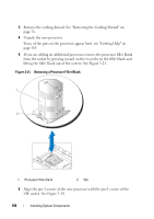
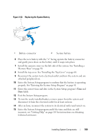
3 Remove the cooling shroud. See "Removing the Cooling Shroud" on page 76. 4 Unpack the new processor. If any of the pins on the processor appear bent, see "Getting Help" on page 165. 5 If you are adding an additional processor, remove the processor filler blank from the socket by pressing inward on the two tabs on the filler blank and lifting the filler blank out of the system. See Figure 3-21. Figure 3-21. Removing a Processor Filler Blank 1 2 1 Processor filler blank 2 Tab 6 Align the pin-1 corner of the new processor with the pin-1 corner of the ZIF socket. See Figure 3-20. 106 Installing System Components
-
 1
1 -
2
-
3
-
4
-
5
-
6
-
7
-
8
-
9
-
10
-
11
-
12
-
13
-
14
-
15
-
16
-
17
-
18
-
19
-
20
-
21
-
22
-
23
-
24
-
25
-
26
-
27
-
28
-
29
-
30
-
31
-
32
-
33
-
34
-
35
-
36
-
37
-
38
-
39
-
40
-
41
-
42
-
43
-
44
-
45
-
46
-
47
-
48
-
49
-
50
-
51
-
52
-
53
-
54
-
55
-
56
-
57
-
58
-
59
-
60
-
61
-
62
-
63
-
64
-
65
-
66
-
67
-
68
-
69
-
70
-
71
-
72
-
73
-
74
-
75
-
76
-
77
-
78
-
79
-
80
-
81
-
82
-
83
-
84
-
85
-
86
-
87
-
88
-
89
-
90
-
91
-
92
-
93
-
94
-
95
-
96
-
97
-
98
-
99
-
100
-
 101
101 -
 102
102 -
 103
103 -
 104
104 -
 105
105 -
 106
106 -
 107
107 -
 108
108 -
 109
109 -
 110
110 -
 111
111 -
112
-
113
-
114
-
115
-
116
-
117
-
118
-
119
-
120
-
121
-
122
-
123
-
124
-
125
-
126
-
127
-
128
-
129
-
130
-
131
-
132
-
133
-
134
-
135
-
136
-
137
-
138
-
139
-
140
-
141
-
142
-
143
-
144
-
145
-
146
-
147
-
148
-
149
-
150
-
151
-
152
-
153
-
154
-
155
-
156
-
157
-
158
-
159
-
160
-
161
-
162
-
163
-
164
-
165
-
166
-
167
-
168
-
169
-
170
-
171
-
172
-
173
-
174
-
175
-
176
-
177
-
178
-
179
-
180
-
181
-
182
-
183
-
184
-
185
-
186
-
187
-
188
-
189
-
190
 |
 |
106
Installing System Components
3
Remove the cooling shroud. See "Removing the Cooling Shroud" on
page 76.
4
Unpack the new processor.
If any of the pins on the processor appear bent, see "Getting Help" on
page 165.
5
If you are adding an additional processor, remove the processor filler blank
from the socket by pressing inward on the two tabs on the filler blank and
lifting the filler blank out of the system. See Figure 3-21.
Figure 3-21.
Removing a Processor Filler Blank
6
Align the pin-1 corner of the new processor with the pin-1 corner of the
ZIF socket. See Figure 3-20.
1
Processor filler blank
2
Tab
1
2