Dell PowerEdge R900 Hardware Owner's Manual (PDF) - Page 64
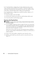
Removing a Hot-Plug Hard Drive, NOTICE
 |
View all Dell PowerEdge R900 manuals
Add to My Manuals
Save this manual to your list of manuals |
Page 64 highlights
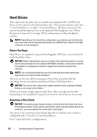
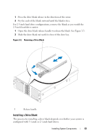
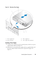
For 3.5-inch hard drive configurations, the drive blank is keyed to ensure correct insertion into the drive bay. To install a 3.5-inch drive blank, insert and rotate in the keyed side of the blank into the drive bay and press evenly on the other end of the blank until it is fully inserted and latched. For 2.5-inch hard drive configurations, install the hard drive blank as a 2.5inch hard drive carrier: 1 Open the handle on the drive blank. 2 Insert the drive blank into the drive bay until the blank is fully seated. 3 Close the handle to lock the blank in place. Removing a Hot-Plug Hard Drive NOTICE: To maintain proper system cooling, all empty hard drive bays must have drive blanks installed. 1 From the RAID management software, prepare the drive for removal and wait until the hard drive indicators on the drive carrier signal that the drive can be removed safely. See your SAS RAID controller documentation for information about hot-plug drive removal. If the drive has been online, the green activity/fault indicator will flash as the drive is powered down. When both drive indicators are off, the drive is ready for removal. 2 Squeeze the carrier handle to unlatch the carrier from the system. 3 Pull the carrier handle away from the system to extract the carrier. See Figure 3-4. 64 Installing System Components
-
 1
1 -
2
-
3
-
4
-
5
-
6
-
7
-
8
-
9
-
10
-
11
-
12
-
13
-
14
-
15
-
16
-
17
-
18
-
19
-
20
-
21
-
22
-
23
-
24
-
25
-
26
-
27
-
28
-
29
-
30
-
31
-
32
-
33
-
34
-
35
-
36
-
37
-
38
-
39
-
40
-
41
-
42
-
43
-
44
-
45
-
46
-
47
-
48
-
49
-
50
-
51
-
52
-
53
-
54
-
55
-
56
-
57
-
58
-
 59
59 -
 60
60 -
 61
61 -
 62
62 -
 63
63 -
 64
64 -
 65
65 -
 66
66 -
 67
67 -
 68
68 -
 69
69 -
70
-
71
-
72
-
73
-
74
-
75
-
76
-
77
-
78
-
79
-
80
-
81
-
82
-
83
-
84
-
85
-
86
-
87
-
88
-
89
-
90
-
91
-
92
-
93
-
94
-
95
-
96
-
97
-
98
-
99
-
100
-
101
-
102
-
103
-
104
-
105
-
106
-
107
-
108
-
109
-
110
-
111
-
112
-
113
-
114
-
115
-
116
-
117
-
118
-
119
-
120
-
121
-
122
-
123
-
124
-
125
-
126
-
127
-
128
-
129
-
130
-
131
-
132
-
133
-
134
-
135
-
136
-
137
-
138
-
139
-
140
-
141
-
142
-
143
-
144
-
145
-
146
-
147
-
148
-
149
-
150
-
151
-
152
-
153
-
154
-
155
-
156
-
157
-
158
-
159
-
160
-
161
-
162
-
163
-
164
-
165
-
166
-
167
-
168
-
169
-
170
-
171
-
172
-
173
-
174
-
175
-
176
-
177
-
178
-
179
-
180
-
181
-
182
-
183
-
184
-
185
-
186
-
187
-
188
-
189
-
190
 |
 |