Dell PowerEdge R900 Hardware Owner's Manual (PDF) - Page 92
Installing an Optical Drive Into an Optical Drive Mounting Tray, System Memory
 |
View all Dell PowerEdge R900 manuals
Add to My Manuals
Save this manual to your list of manuals |
Page 92 highlights
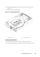
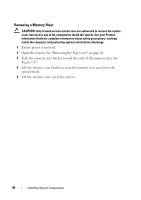
Installing an Optical Drive Into an Optical Drive Mounting Tray 1 Slide the optical drive onto the left side alignment pins of the optical drive mounting tray. 2 Angle the retaining bracket tab into the optical drive mounting tray notch. 3 Press the retaining bracket against the optical drive, ensuring the alignment pin engages the optical drive hole. NOTE: The alignment pin on the retaining bracket must engage a hole in the optical drive. 4 Screw the optical drive retaining screw into the optical drive mounting tray. 5 Connect the ribbon cable to the back of the optical drive. System Memory The system supports x4 or x8, single- or dual-rank fully buffered 667 MT/s (55-5 latency) DDR2 DIMMs in 512 MB, 1 GB, 2 GB, or 4 GB packages. Four memory risers must be installed at all times. The risers connect to the main board through x16 PCI Express connectors. General Memory Module Installation Guidelines AC power must be removed from the system before servicing the memory risers. NOTICE: For proper cooling, each memory riser must be fully populated with DIMMs or blanks or a combination thereof. Four memory risers with one DIMM per riser must be installed for the server to function. Supported memory riser configurations are as follows: • All DIMMs must be FBD using DDR2 DRAMs (FBD Generation 1). • In all cases, DIMMs must be installed starting with the lowest number slot in a given channel (i.e., install DIMM1 first). • In non-Mirrored Mode, all DIMMs with the same slot number within a given branch must match (size, technology, etc.). It is not required to match DIMMs between different slot numbers. 92 Installing System Components
-
 1
1 -
2
-
3
-
4
-
5
-
6
-
7
-
8
-
9
-
10
-
11
-
12
-
13
-
14
-
15
-
16
-
17
-
18
-
19
-
20
-
21
-
22
-
23
-
24
-
25
-
26
-
27
-
28
-
29
-
30
-
31
-
32
-
33
-
34
-
35
-
36
-
37
-
38
-
39
-
40
-
41
-
42
-
43
-
44
-
45
-
46
-
47
-
48
-
49
-
50
-
51
-
52
-
53
-
54
-
55
-
56
-
57
-
58
-
59
-
60
-
61
-
62
-
63
-
64
-
65
-
66
-
67
-
68
-
69
-
70
-
71
-
72
-
73
-
74
-
75
-
76
-
77
-
78
-
79
-
80
-
81
-
82
-
83
-
84
-
85
-
86
-
 87
87 -
 88
88 -
 89
89 -
 90
90 -
 91
91 -
 92
92 -
 93
93 -
 94
94 -
 95
95 -
 96
96 -
 97
97 -
98
-
99
-
100
-
101
-
102
-
103
-
104
-
105
-
106
-
107
-
108
-
109
-
110
-
111
-
112
-
113
-
114
-
115
-
116
-
117
-
118
-
119
-
120
-
121
-
122
-
123
-
124
-
125
-
126
-
127
-
128
-
129
-
130
-
131
-
132
-
133
-
134
-
135
-
136
-
137
-
138
-
139
-
140
-
141
-
142
-
143
-
144
-
145
-
146
-
147
-
148
-
149
-
150
-
151
-
152
-
153
-
154
-
155
-
156
-
157
-
158
-
159
-
160
-
161
-
162
-
163
-
164
-
165
-
166
-
167
-
168
-
169
-
170
-
171
-
172
-
173
-
174
-
175
-
176
-
177
-
178
-
179
-
180
-
181
-
182
-
183
-
184
-
185
-
186
-
187
-
188
-
189
-
190
 |
 |