Dell PowerEdge T710 Hardware Owner's Manual
Dell PowerEdge T710 Manual
 |
View all Dell PowerEdge T710 manuals
Add to My Manuals
Save this manual to your list of manuals |
Dell PowerEdge T710 manual content summary:
- Dell PowerEdge T710 | Hardware Owner's Manual - Page 1
Dell™ PowerEdge™ T710 Systems Hardware Owner's Manual - Dell PowerEdge T710 | Hardware Owner's Manual - Page 2
computer. CAUTION: A CAUTION indicates potential damage to hardware or loss of data if instructions are not followed. WARNING: A WARNING indicates a permission of Dell Inc. is strictly forbidden. Trademarks used in this text: Dell, the DELL logo, and PowerEdge are trademarks of Dell Inc.; Microsoft - Dell PowerEdge T710 | Hardware Owner's Manual - Page 3
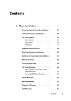
Features 14 Home Screen 16 Setup Menu 16 View Menu 17 Hard-Drive Status Indicators 18 Back-Panel Features and Indicators 20 Guidelines for Connecting External Devices 22 NIC Indicator Codes 23 Power Indicator Codes 24 LCD Status Messages 25 Solving Problems Described by LCD Status Messages - Dell PowerEdge T710 | Hardware Owner's Manual - Page 4
Boot Manager 57 Choosing the System Boot Mode 57 Entering the System Setup Program 58 Responding to Error Messages 58 Using the System Setup Program Navigation Keys 58 System Setup Options 59 Main Screen 59 Memory Settings Screen 61 Processor Settings Screen 62 SATA Settings Screen 63 Boot - Dell PowerEdge T710 | Hardware Owner's Manual - Page 5
Setup Password 75 Embedded System Management 76 iDRAC Configuration Utility 77 Entering the iDRAC Configuration Utility 77 3 Installing System Components 79 Recommended Tools 79 Inside the System 79 Power Supplies 81 Removing a Power Supply 82 Installing a Power Supply 83 Removing a Power - Dell PowerEdge T710 | Hardware Owner's Manual - Page 6
a Hot-Swap Hard Drive 91 Removing a Hard Drive From a Hard-Drive Carrier 92 Installing a Hard Drive Into a Hard-Drive Carrier 93 Optical and Tape Drives 94 Removing an Optical or a Tape Drive 94 Installing an Optical or Tape Drive 96 System Memory 98 General Memory Module Installation - Dell PowerEdge T710 | Hardware Owner's Manual - Page 7
Fan Cage 139 VFlash Media (Optional 140 Installing a VFlash Media 140 Removing a VFlash Media 140 Integrated Dell Remote Access Controller 6 (iDRAC6) Enterprise Card (Optional 140 Installing an iDRAC6 Enterprise Card 140 Removing an iDRAC6 Enterprise Card 142 System Battery 144 Replacing - Dell PowerEdge T710 | Hardware Owner's Manual - Page 8
159 Troubleshooting External Connections 159 Troubleshooting the Video Subsystem 160 Troubleshooting a USB Device 160 Troubleshooting a Serial I/O Device 161 Troubleshooting a NIC 161 Troubleshooting a Wet System 162 Troubleshooting a Damaged System 164 Troubleshooting the System Battery 165 - Dell PowerEdge T710 | Hardware Owner's Manual - Page 9
Troubleshooting Power Supplies 165 Troubleshooting System Cooling Problems 166 Troubleshooting a Fan 166 Troubleshooting System Memory 167 Troubleshooting an Internal SD Card 169 Troubleshooting an Internal USB Memory Key . . . . . 170 Troubleshooting an Optical Drive 171 Troubleshooting a - Dell PowerEdge T710 | Hardware Owner's Manual - Page 10
and Results 184 6 Jumpers and Connectors 185 System Board Jumpers 185 System Board Connectors 186 SAS Backplane Board Connectors 189 Power Distribution Board Connectors 191 Disabling a Forgotten Password 192 7 Getting Help 193 Contacting Dell 193 Glossary 195 Index 205 10 Contents - Dell PowerEdge T710 | Hardware Owner's Manual - Page 11
on the system's boot configuration. See "Using the System Setup Program and UEFI Boot Manager" on page 57. Starts PXE boot. Enters the Baseboard Management Controller (BMC) or iDRAC Configuration Utility, which allows access to the system event log (SEL) and configuration of remote access to the - Dell PowerEdge T710 | Hardware Owner's Manual - Page 12
hard drives. Connects USB devices to the system. The ports are USB 2.0-compliant. Used to troubleshoot software and device driver errors when using certain operating systems. This button can be pressed using the end of a paper clip. Use this button only if directed to do so by qualified support - Dell PowerEdge T710 | Hardware Owner's Manual - Page 13
button 5 System identification button 6 LCD menu buttons Description The power-on indicator lights when the system power is on. The power button controls the DC power supply output to the system. NOTE: When powering on the system, the video monitor can take up to 25 seconds to display an image - Dell PowerEdge T710 | Hardware Owner's Manual - Page 14
and the LCD panel displays an error code followed by descriptive text. NOTE: If the system is connected to AC power and an error has been detected, the LCD lights amber regardless of whether the system has been powered on. One or two optional SATA DVD-ROM or DVD+RW drives. NOTE: DVD devices are data - Dell PowerEdge T710 | Hardware Owner's Manual - Page 15
speed. • Press again to repeat the cycle. 4 System identification Turns the system ID mode on (LCD panel flashes blue) and off. Press quickly to toggle the system ID on and off. If the system hangs during POST, press and hold the system ID button for more than five seconds to enter BIOS - Dell PowerEdge T710 | Hardware Owner's Manual - Page 16
DHCP or Static IP to configure the network mode. If Static IP is selected, the available fields are IP, Subnet (Sub), and Gateway (Gtw). Select Setup DNS to enable DNS and to view domain addresses. Two separate DNS entries are available. Select SEL to display LCD error messages in a format that - Dell PowerEdge T710 | Hardware Owner's Manual - Page 17
DRAC IP MAC Name Number Power Temperature Description Displays the IPv6 addresses for the iDRAC6. Addresses include DNS ( Service tag for the system. Displays the power output of the system in BTU/hr or Watts. The display format can be configured in the Set home submenu of the Setup menu. See "Setup - Dell PowerEdge T710 | Hardware Owner's Manual - Page 18
Hard-Drive Status Indicators Figure 1-3. Hard-Drive Indicators 1 2 1 2 3.5-in carrier 1 drive-activity indicator (green) 2.5-in carrier 2 drive-status indicator (green and amber) 18 About Your System - Dell PowerEdge T710 | Hardware Owner's Manual - Page 19
, amber three seconds, and off six seconds. Condition Identify drive/preparing for removal Drive ready for insertion or removal NOTE: The drive status indicator remains off until all hard drives are initialized after system power is applied. Drives are not ready for insertion or removal during this - Dell PowerEdge T710 | Hardware Owner's Manual - Page 20
Back-Panel Features and Indicators Figure 1-4. Back-Panel Features and Indicators 1 2 3 4 5 6 7 8 9 10 11 20 About Your System - Dell PowerEdge T710 | Hardware Owner's Manual - Page 21
x8 (x8 routing, Gen 2), half-length. Slot 6: PCIe x8 (x8 routing, Gen 2), half-length. 1100-W power supply. The identification buttons on the front and back panels can be used to locate a particular system within a rack. When one of these buttons is pushed, the LCD panel on the front and the system - Dell PowerEdge T710 | Hardware Owner's Manual - Page 22
Enterprise card. Connects an external SD memory card for the optional iDRAC6 Enterprise card. Connects USB devices to the system. The ports are USB 2.0-compliant. Connects a cable lock to the system. Guidelines for Connecting External Devices • Turn off power to the system and external devices - Dell PowerEdge T710 | Hardware Owner's Manual - Page 23
2 1 link indicator 2 activity indicator Indicator Indicator Code Link and activity indicators are off The NIC is not connected to the network. Link indicator is green The NIC is connected to a valid network - Dell PowerEdge T710 | Hardware Owner's Manual - Page 24
to the power supply and that the power supply is operational. When the system is on, a green light also indicates that the power supply is providing DC power to the system. • Amber - Indicates a problem with the power supply. Figure 1-6. Power Supply Status Indicator 1 1 power supply status 24 - Dell PowerEdge T710 | Hardware Owner's Manual - Page 25
the system event voltage error. log for critical failure Contact events. support. Remove AC power to the system for 10 seconds and restart the system. If the problem persists, see "Getting Help" on page 193. E1114 Ambient Temp Ambient temperature has See "Troubleshooting exceeds a reached - Dell PowerEdge T710 | Hardware Owner's Manual - Page 26
165. battery. E1211 RAID RAID battery is either Reseat the RAID battery Controller missing, bad, or unable to connector. See "Installing battery recharge due to thermal a RAID Battery" on failure. Check issues. page 128, and battery. "Troubleshooting System Cooling Problems" on page - Dell PowerEdge T710 | Hardware Owner's Manual - Page 27
"Troubleshooting System Memory" on page 167. E122E On-board regulator failed. Call support. One of the on-board voltage regulators failed. Remove AC power to the system for 10 seconds and restart the system. If the problem persists, see "Getting Help" on page 193. E1310 Fan ## RPM exceeding - Dell PowerEdge T710 | Hardware Owner's Manual - Page 28
specifications outlined in your system's Getting Started Guide. E141F CPU # protocol The system BIOS has error. Power reported a processor cycle AC. protocol error. Remove AC power to the system for 10 seconds and restart the system. If the problem persists, see "Getting Help" on page 193 - Dell PowerEdge T710 | Hardware Owner's Manual - Page 29
Troubleshooting Power Supplies" on page 165. E1614 Power Supply # Specified power supply (### W) error. has failed. Check power supply. See "Troubleshooting Power Supplies" on page 165. E1618 Predictive failure on Power Supply # (### W). Check PSU. An over-temperature condition or power supply - Dell PowerEdge T710 | Hardware Owner's Manual - Page 30
system, reduce the hardware configuration or install higher-wattage power supplies, and then restart the system. E1710 I/O channel check error. Review & clear SEL. The system BIOS has reported an I/O channel check. Check the SEL for more information and then clear the SEL. Remove AC power to the - Dell PowerEdge T710 | Hardware Owner's Manual - Page 31
expansion cards. If on a component that the problem persists, see resides in PCI "Troubleshooting configuration space at bus Expansion Cards" on ##, device ##, function page 178. ##. PCI parity error on Slot #. Review & clear SEL. The system BIOS has Remove and reseat the reported a PCI - Dell PowerEdge T710 | Hardware Owner's Manual - Page 32
hard drive fault. Review has experienced a fault. & clear SEL. See "Troubleshooting a Hard Drive" on page 174. E1812 Hard drive ## The specified hard drive removed. Check has been removed from drive. the system. Information only. E1920 iDRAC6 Upgrade The iDRAC6 Express card If the problem - Dell PowerEdge T710 | Hardware Owner's Manual - Page 33
configured but unusable. System Memory" on unusable. page 167. Check DIMMs. E2013 BIOS unable to The system BIOS failed to See "Troubleshooting shadow memory. copy its flash image into System Memory" on Check DIMMs. memory. page 167. E2014 CMOS RAM CMOS failure. CMOS failure. Power RAM - Dell PowerEdge T710 | Hardware Owner's Manual - Page 34
Status Messages (continued) Code Text E2018 Programmable Timer error. Power cycle AC. Causes Programmable interval timer error. E2019 Parity error. Parity error. Power cycle AC. E201A SuperIO SIO failure. failure. Power cycle AC. E201B Keyboard Controller error. Power cycle AC. Keyboard - Dell PowerEdge T710 | Hardware Owner's Manual - Page 35
memory configuration. configuration. Review User Guide. Check screen for specific error messages. See "Troubleshooting System Memory" on page 167. E2022 General General failure after video. Check screen for specific failure during error messages. POST. Check screen message. E2023 BIOS - Dell PowerEdge T710 | Hardware Owner's Manual - Page 36
had too many If the problem persists, errors. "##" represents the see "Troubleshooting memory module System Memory" on implicated by the BIOS. page 167. E2113 Mem mirror OFF on DIMM ## & ##. Power cycle AC The system BIOS has Remove AC power to the disabled memory system for 10 seconds and - Dell PowerEdge T710 | Hardware Owner's Manual - Page 37
charge. If problem persists, replace RAID battery. See "Installing a RAID Battery" on page 128. W1627 Power required The system configuration Turn off power to the > PSU wattage. requires more power than system, reduce the Check PSU and what the power supply can hardware configuration or config - Dell PowerEdge T710 | Hardware Owner's Manual - Page 38
if multiple related errors occur. For example, if you receive a series of messages indicating multiple voltage faults, you might determine that the problem is a failing power supply. Removing LCD Status Messages For faults associated with sensors, such as temperature, voltage, fans, and so on - Dell PowerEdge T710 | Hardware Owner's Manual - Page 39
in a configuration that supports Advanced ECC Memory Mode. Check other system messages for additional information for possible causes. For memory configuration information, see "General Memory Module Installation Guidelines" on page 98. If the problem persists, see "Troubleshooting System Memory" on - Dell PowerEdge T710 | Hardware Owner's Manual - Page 40
not Wait for the system to responding to BIOS reboot. communication either because it is not functioning properly or has not completed initialization. The system will reboot. Alert! iDRAC6 not responding. Power required may exceed PSU wattage. Alert! Continuing system boot accepts the risk - Dell PowerEdge T710 | Hardware Owner's Manual - Page 41
Alert! Power required exceeds PSU wattage. Check PSU and system configuration. Alert! Continuing system boot accepts the risk that system may power down without warning. The system configuration of processor(s), memory modules, and expansion cards may not be supported by the power supplies. If - Dell PowerEdge T710 | Hardware Owner's Manual - Page 42
of manufacturing mode. BIOS Update Remote BIOS update Attempt Failed! attempt failed. Retry the BIOS update. If problem persists, see "Getting Help" on page 193. Caution! NVRAM_CLR jumper is installed on system board. Please run SETUP NVRAM_CLR jumper is installed in the clear setting. CMOS - Dell PowerEdge T710 | Hardware Owner's Manual - Page 43
different power BIOS and the proper Setup Program and UEFI Boot Manager" on the system setup page 57. program to change the boot mode as needed. Decreasing available memory Faulty or improperly installed Reseat the memory modules. memory modules. See "Troubleshooting System Memory - Dell PowerEdge T710 | Hardware Owner's Manual - Page 44
or keyboard is operational. See "Troubleshooting a USB Device" on page 160. Gate A20 failure Faulty keyboard controller; See "Getting Help" on faulty system board. page 193. Invalid configuration information please run SETUP program. An invalid system configuration caused a system halt. Run - Dell PowerEdge T710 | Hardware Owner's Manual - Page 45
enable the USB port(s). See "Entering the System Setup Program" on page 58. Manufacturing mode detected System is in manufacturing Reboot to take the system mode. out of manufacturing mode. Maximum rank count exceeded. The following DIMM has been disabled: x Invalid memory configuration. The - Dell PowerEdge T710 | Hardware Owner's Manual - Page 46
If not an intentional setting, be intentionally set lower for check any other system power conservation. messages for possible causes. The current memory Ensure that your memory configuration may support configuration supports the only the minimum frequency. higher frequency. See "General - Dell PowerEdge T710 | Hardware Owner's Manual - Page 47
key installed. Use a bootable USB key, optical drive, or hard drive. If the problem persists, see "Troubleshooting an Optical Drive" on page 171, "Troubleshooting a USB Device" on page 160, and "Troubleshooting a Hard Drive" on page 174. See "Using the System Setup Program and UEFI Boot Manager" on - Dell PowerEdge T710 | Hardware Owner's Manual - Page 48
are installed in a valid configuration. See "General Memory Module Installation Guidelines" on page 98. Read fault Requested sector not found The operating system cannot Replace the optical medium, read from the hard drive, USB medium, or USB optical drive, or USB device, device. Ensure that - Dell PowerEdge T710 | Hardware Owner's Manual - Page 49
Sector not found Faulty hard drive, USB Seek error device, or USB medium. Seek operation failed Replace the USB medium or device. Ensure that the USB or SAS backplane cables are properly connected. See "Troubleshooting a USB Device" on page 160 or "Troubleshooting a Hard Drive" on page 174 for - Dell PowerEdge T710 | Hardware Owner's Manual - Page 50
"Troubleshooting the System Battery" on page 165. Time-of-day not Incorrect Time or Date set - please run settings; faulty system SETUP program battery. Check the Time and Date settings. See "Using the System Setup Program and UEFI Boot Manager" on page 57. If the problem persists, replace the - Dell PowerEdge T710 | Hardware Owner's Manual - Page 51
is pending. Press (I) to Ignore OR (M) to Modify to This message displays during Enter I or M to proceed. system restart after a TPM configuration command has been entered. User interaction is required to proceed. allow this change and reset the system. WARNING: Modifying could prevent security - Dell PowerEdge T710 | Hardware Owner's Manual - Page 52
support.dell.com. See the iDRAC6 user's guide for instructions on performing a field replacement of the flash memory. Unexpected interrupt in protected mode Improperly seated memory modules or faulty keyboard/mouse controller chip. Reseat the memory modules. See "Troubleshooting System Memory - Dell PowerEdge T710 | Hardware Owner's Manual - Page 53
mode to Optimized available when in or Sparing in the BIOS setup 128-Bit Advanced screen. See "System ECC mode: Memory" on page 98. Warning: A fatal A fatal system error occurred Check the SEL for error has caused and caused the system to information that was logged system reset! reboot - Dell PowerEdge T710 | Hardware Owner's Manual - Page 54
. Warning! No micro Micro code update failed. code update loaded for processor n Update the BIOS firmware. See "Getting Help" on page 193. Warning! Power required exceeds PSU wattage. Check PSU and system configuration. Warning! Performance degraded. CPU and memory set to minimum frequencies to - Dell PowerEdge T710 | Hardware Owner's Manual - Page 55
Guidelines" on page 98. If the problem persists, see "Troubleshooting System Memory" on page 167. Write fault Write fault on selected drive Faulty USB device, USB Replace the USB medium or medium, optical drive device. Ensure that the USB, assembly, hard drive, or hard- SAS backplane, or SATA - Dell PowerEdge T710 | Hardware Owner's Manual - Page 56
and tools for configuring and managing your system, including those pertaining to the operating system, system management software, system updates, and system components that you purchased with your system. NOTE: Always check for updates on support.dell.com/manuals and read the updates first because - Dell PowerEdge T710 | Hardware Owner's Manual - Page 57
Setup program to familiarize yourself with your system configuration and to: • Change the NVRAM settings after you add or remove hardware 64-bit boot interface based on Unified Extensible Firmware Interface (UEFI) specifications that overlays the system BIOS. See "Entering the UEFI Boot Manager" on - Dell PowerEdge T710 | Hardware Owner's Manual - Page 58
an explanation of the message and suggestions for correcting errors. NOTE: After installing a memory upgrade, it is normal for your system to display a Exits the System Setup program and restarts the system if any changes were made. Displays the System Setup program's help file. NOTE: - Dell PowerEdge T710 | Hardware Owner's Manual - Page 59
for the System Setup program change based on the system configuration. Option System Time System Date Memory Settings Processor Settings SATA Displays information related to installed memory. See "Memory Settings Screen" on page 61. Displays information related to processors (speed, cache, and so - Dell PowerEdge T710 | Hardware Owner's Manual - Page 60
(Optional)" on page 66. Enables you to manage power usage of the processor(s), fans, and memory modules with preconfigured or customized settings. See "Power Management Screen" on page 66. Displays a screen to configure the system password and setup password features. See "System Security Screen" on - Dell PowerEdge T710 | Hardware Owner's Manual - Page 61
interleaving is supported if a symmetric memory configuration is installed. If Disabled, the system supports Non-Uniform Memory architecture (NUMA) (asymmetric) memory configurations. NOTE: The Node Interleaving field must be set to Disabled when using Mirror mode. Using the System Setup Program - Dell PowerEdge T710 | Hardware Owner's Manual - Page 62
the processor clock speed. Bus Speed Displays the processor bus speed. Logical Processor (Enabled default) On processors that support Simultaneous MultiThreading (SMT) technology, each processor core supports up to two logical processors. If this field is set to Enabled, the BIOS reports both - Dell PowerEdge T710 | Hardware Owner's Manual - Page 63
operating system supports Unified Extensible Firmware Interface, you can set this option to UEFI. Setting this field to BIOS allows compatibility with non-UEFI operating systems. NOTE: Setting this field to UEFI disables the Boot Sequence, Hard-Disk Drive Sequence, and USB Flash Drive Emulation Type - Dell PowerEdge T710 | Hardware Owner's Manual - Page 64
RAID Controller (Enabled default) Enables or disables the integrated storage controller. User Accessible USB Ports Enables or disables the user accessible USB only with operating systems that support WDAT implementations of the Advanced Configuration and Power Interface (ACPI) 3.0b specification - Dell PowerEdge T710 | Hardware Owner's Manual - Page 65
Enables or disables BIOS support for the integrated video controller. NOTE: This keys to manually select an IRQ for a given device, or select Default to allow the BIOS to select an or disables BIOS console redirection after the operating system boots. Using the System Setup Program and UEFI - Dell PowerEdge T710 | Hardware Owner's Manual - Page 66
Maximum Performance. For all but the Custom setting, the BIOS pre-configures the power settings on this screen as follows: • OS Control sets the CPU power to OS DBPM, the fan power to Minimum Power, and the memory power to Maximum Performance. In this setting, all processor performance information - Dell PowerEdge T710 | Hardware Owner's Manual - Page 67
Options are OS DBPM, System DBPM, Maximum Performance Management Performance, or Minimum Power. Fan Power and Options are Maximum Performance or Minimum Performance Management Power. Memory Power and Options are Maximum Performance, a specified Performance Management frequency, or Minimum - Dell PowerEdge T710 | Hardware Owner's Manual - Page 68
TPM keys prior to enabling this option. When set to Yes, all TPM contents are cleared. NOTE: This field is read-only when TPM Security is set to Off. If Enabled, the power button can turn the system's power off and on. On an ACPI-compliant operating system, the system performs an orderly - Dell PowerEdge T710 | Hardware Owner's Manual - Page 69
power state. On turns on the system after power is restored. Off allows the system to remain off after power is restored. AC Power Recovery Delay Determines when the system restarts after power arrange boot options • Access the System Setup program and BIOS-level boot options without rebooting 1 - Dell PowerEdge T710 | Hardware Owner's Manual - Page 70
. Enables you to add, delete, enable, or disable boot options; change boot order; or execute a one-time boot option. Enables you to access the System Setup program, System Services (Unified Server Configurator (USC)), Diagnostics, and BIOS-level boot options. 70 Using the System - Dell PowerEdge T710 | Hardware Owner's Manual - Page 71
boot option list. System Utilities Screen Option System Setup System Services (USC) BIOS Boot Manager Reboot System Description Accesses the System Setup program without rebooting. Restarts the system and accesses the Unified Server Configurator, which allows you to run utilities such as system - Dell PowerEdge T710 | Hardware Owner's Manual - Page 72
and only those with the password have full use of the system. Assigning a System Password Before assigning a system password, enter the System Setup program and check the System Password option. When a system password is assigned, System Password is Enabled. If Password Status is Unlocked, you - Dell PowerEdge T710 | Hardware Owner's Manual - Page 73
step 5. 4 Press . 5 To confirm your password, type it a second time and press . System Password changes to Enabled. Exit the System Setup program and begin using your system. 6 Either reboot the system now for the password protection to take effect or continue working. NOTE: Password - Dell PowerEdge T710 | Hardware Owner's Manual - Page 74
after you shut down and restart the system, the error message continues to be displayed until the correct password is entered. NOTE: You can use the Password Status option in conjunction with the System Password and Setup Password options to protect your system from unauthorized changes. Deleting - Dell PowerEdge T710 | Hardware Owner's Manual - Page 75
options. If you do not enter the correct password in three attempts, the system lets you view, but not modify, the System Setup screens. The following options are exceptions: If System Password is not Enabled and is not locked through the Password Status option, you can assign a system - Dell PowerEdge T710 | Hardware Owner's Manual - Page 76
updates • Configuring hardware and firmware For more information about setting up USC, configuring hardware and firmware, and deploying the operating system, see the Dell Unified Server Configurator User's Guide on the Dell Support website at support.dell.com/manuals. 76 Using the System Setup - Dell PowerEdge T710 | Hardware Owner's Manual - Page 77
and manage user privileges • View System Event Log (SEL) messages or clear messages from the log For additional information on using iDRAC6, see the documentation for iDRAC6 and systems management applications. Entering the iDRAC Configuration Utility 1 Turn on or restart your system. 2 Press - Dell PowerEdge T710 | Hardware Owner's Manual - Page 78
78 Using the System Setup Program and UEFI Boot Manager - Dell PowerEdge T710 | Hardware Owner's Manual - Page 79
is in a rack configuration, disregard any steps for laying the system on its side and rotating the system feet. Recommended Tools • Key to the system keylock • #1 and #2 Phillips screwdrivers • T10 Torx driver • Wrist grounding strap Inside the System WARNING: Only trained service technicians are - Dell PowerEdge T710 | Hardware Owner's Manual - Page 80
Figure 3-1. Inside the System 17 16 15 14 13 12 11 10 9 1 2 3 4 5 6 7 8 80 Installing System Components - Dell PowerEdge T710 | Hardware Owner's Manual - Page 81
15 RAID battery (optional) 17 integrated storage controller card 2 cooling shroud 4 cooling fan modules (4) 6 memory modules (up to 18 total, 9 for each processor) 8 heat sink and processor (1 or 2) 10 control panel 12 optical drive 14 SAS backplane 16 chassis intrusion switch Power Supplies Your - Dell PowerEdge T710 | Hardware Owner's Manual - Page 82
and lift the optional cable management arm if it interferes with power supply removal. For information about the cable management arm, see the system's rack documentation. 1 Disconnect the power cable from the power source and the power supply you intend to remove, and remove the cables from the - Dell PowerEdge T710 | Hardware Owner's Manual - Page 83
in the second power supply bay in a non-redundant configuration. Remove the power supply blank only if you are installing a second power supply. Installing a Power Supply Blank NOTE: Install the power supply blank only in the second power supply bay. To install the power supply blank, align the - Dell PowerEdge T710 | Hardware Owner's Manual - Page 84
If you are removing or installing a hot-swappable hard drive, the system may remain turned on and in the bezel (if locked). 2 Slide the release latch in the direction of the arrow and rotate the top end of the bezel away from the chassis. 3 Lift the bezel away from the chassis. Figure 3-3. Removing - Dell PowerEdge T710 | Hardware Owner's Manual - Page 85
the safety instructions that came with the system. WARNING: Whenever you need to lift the system, get others to assist you. To avoid injury, do not attempt to lift the system by yourself. Opening the System 1 Unless you are removing a hot-swap component such as a hard drive or a power supply, turn - Dell PowerEdge T710 | Hardware Owner's Manual - Page 86
Figure 3-4. Opening and Closing the System 2 3 1 4 1 cover release latch 3 system cover 2 cover release latch lock 4 system feet (4) Closing the System 1 Ensure that all internal cables are connected and folded out of the way. 2 Ensure that no tools or extra parts are left inside the system. 3 - Dell PowerEdge T710 | Hardware Owner's Manual - Page 87
modules. WARNING: Only trained service technicians are authorized to remove the system cover and access any of the components inside the system. Before you begin this procedure, review the safety instructions that came with the system. WARNING: The memory modules and heat sink can get very hot - Dell PowerEdge T710 | Hardware Owner's Manual - Page 88
and Installing the Cooling Shroud 2 1 1 cooling shroud 2 cooling shroud release tab Installing the Cooling Shroud 1 Align the cooling shroud with the alignment guides in the system. 2 Carefully lower the cooling shroud into the system until the securing tab snaps over the shroud using the tab - Dell PowerEdge T710 | Hardware Owner's Manual - Page 89
are supplied in special hotswappable hard-drive carriers that fit in the hard-drive bays. CAUTION: Before attempting to remove or install a drive while the system is running, see the documentation for the storage controller card to ensure that the host adapter is configured correctly to support hot - Dell PowerEdge T710 | Hardware Owner's Manual - Page 90
hard drive blank Installing a Hard-Drive Blank Align the hard-drive blank with the drive bay and insert the blank into the drive bay until the release lever clicks into place. Removing a Hot-Swap Hard Drive CAUTION: To prevent data loss, ensure that your operating system supports hotswap drive - Dell PowerEdge T710 | Hardware Owner's Manual - Page 91
page 84. 2 From the RAID management software, prepare the drive for removal. Wait until the hard-drive indicators on the hard-drive carrier signal that the drive can be removed safely. See your controller documentation for information about hot-swap drive removal. If the drive has been online, the - Dell PowerEdge T710 | Hardware Owner's Manual - Page 92
handle to lock the drive in place. 4 Replace the front bezel. See "Installing the Front Bezel" on page 85. Removing a Hard Drive From a Hard-Drive Carrier Remove the screws from the slide rails on the hard-drive carrier and separate the hard drive from the carrier. See Figure 3-8. 92 Installing - Dell PowerEdge T710 | Hardware Owner's Manual - Page 93
a Hard Drive Into a Hard-Drive Carrier 1 Insert the hard drive into the hard-drive carrier with the connector end of the drive at the back. See Figure 3-8. 2 Align the screw holes on the hard drive with the set of holes on the harddrive carrier. When aligned correctly, the back of the hard drive - Dell PowerEdge T710 | Hardware Owner's Manual - Page 94
on page 96. If the drive is being permanently removed, install the blank carrier in the slot. 8 Close the system. See "Closing the System" on page 86. 9 Place the system upright and on its feet on a flat, stable surface. 10 Rotate the system feet outward. 11 Replace the front bezel. See "Installing - Dell PowerEdge T710 | Hardware Owner's Manual - Page 95
Figure 3-9. Removing and Installing an Optical or Tape Drive 5 4 3 2 1 1 optical drive 3 drive bay screw slots 5 power and data cables 2 shoulder screws (3) 4 drive release latch Installing System Components 95 - Dell PowerEdge T710 | Hardware Owner's Manual - Page 96
Card" on page 115. Tape drives cannot be connected to the integrated storage controller card. If you are installing a SCSI tape drive, you must have a SCSI controller card installed. See "Installing an Expansion Card" on page 115. You must configure the tape drive according to the documentation that - Dell PowerEdge T710 | Hardware Owner's Manual - Page 97
with the slots in the chassis and slide the drive into the drive bay until the shoulder screws snap into place. See Figure 3-9. 9 Attach the power and data cables to the drive. 10 Close the system. See "Closing the System" on page 86. 11 Replace the front bezel. See "Installing the Front Bezel" on - Dell PowerEdge T710 | Hardware Owner's Manual - Page 98
• 1-GB and 2-GB UDIMMs are supported for a total of up to 24 GB. General Memory Module Installation Guidelines To ensure optimal performance of your system, observe the following general guidelines when configuring your system memory. NOTE: Memory configurations that fail to observe these guidelines - Dell PowerEdge T710 | Hardware Owner's Manual - Page 99
device widths. • The memory speed of each channel depends on the memory configuration: - For single or dual-rank memory modules: • One memory module per channel supports up to 1333 MHz. • Two memory modules per channel supports up to 1067 MHz. • Three memory modules per channel supports up to 800 - Dell PowerEdge T710 | Hardware Owner's Manual - Page 100
Memory Mirroring Support The system supports memory mirroring if identical memory modules are installed in the two channels closest to the processor (memory should not be installed in the farthest channel). Mirroring must be enabled in the System Setup program. In a mirrored configuration, the total - Dell PowerEdge T710 | Hardware Owner's Manual - Page 101
Sample RDIMM Single- and Dual-Rank Memory Configurations (Per Processor) (continued) Memory Mode Memory Module Size Memory Sockets Single Processor Dual Processor 1 2 3 Physical Available Physical Available 4 5 6 Memory Memory Memory Memory 7 8 9 (GB) (GB) (GB) (GB) Optimizer 4-GB - Dell PowerEdge T710 | Hardware Owner's Manual - Page 102
Sample RDIMM Single- and Dual-Rank Memory Configurations (Per Processor) (continued) Memory Mode Memory Module Size Memory Sockets Single Processor Dual Processor 1 2 3 Physical Available Physical Available 4 5 6 Memory Memory Memory Memory 7 8 9 (GB) (GB) (GB) (GB) Advanced 8-GB - Dell PowerEdge T710 | Hardware Owner's Manual - Page 103
Table 3-2. Sample UDIMM Memory Configurations (Per Processor) Memory Mode Memory Memory Sockets Single Processor Dual Processor Module Size 1 4 2 5 3 6 Physical Available Physical Available Memory Memory Memory Memory 7 8 9 (GB) (GB) (GB) (GB) Optimizer 1-GB X X X XX XX X X XX XX X - Dell PowerEdge T710 | Hardware Owner's Manual - Page 104
begin this procedure, review the safety instructions that came with the system. WARNING: The memory modules are hot to the touch for some time after the system has been powered down. Allow time for the memory modules to cool before handling them. Handle the memory modules by the card edges and avoid - Dell PowerEdge T710 | Hardware Owner's Manual - Page 105
3-11. Installing and Removing a Memory Module 1 2 3 1 memory module 3 alignment key 2 memory module socket levers (2) 7 Align the memory module's edge connector with the alignment key of the memory module socket, and insert the memory module in the socket. NOTE: The memory module socket has an - Dell PowerEdge T710 | Hardware Owner's Manual - Page 106
the System Diagnostics" on page 181. Removing Memory Modules WARNING: Only trained service technicians are authorized to remove the system cover and access any of the components inside the system. Before you begin this procedure, review the safety instructions that came with the system. WARNING: The - Dell PowerEdge T710 | Hardware Owner's Manual - Page 107
instructions that came with the system. 1 Prior to upgrading your system, download the latest system BIOS version from support.dell.com and follow the instructions included in the compressed download file to install the update some time after the system has been powered down. Allow the heat sink and - Dell PowerEdge T710 | Hardware Owner's Manual - Page 108
8 Gently lift the heat sink off of the processor and set the heat sink aside upside down (thermal grease side facing up). Figure 3-12. Installing and Removing the Heat Sink 1 2 1 heat sink 2 release lever (2) CAUTION: The processor is held in its socket under strong pressure. Be aware that the - Dell PowerEdge T710 | Hardware Owner's Manual - Page 109
Figure 3-13. Removing a Processor 2 3 1 4 1 socket-release lever 3 processor shield 2 processor 4 ZIF socket CAUTION: Be careful not to bend any of the pins on the ZIF socket when removing the processor. Bending the pins can permanently damage the system board. 11 Carefully, lift the processor - Dell PowerEdge T710 | Hardware Owner's Manual - Page 110
Processor WARNING: Only trained service technicians are authorized to remove the system cover and access any of the components inside the system. Before you begin this procedure, review the safety instructions that came with the system. NOTE: In a single-processor configuration, the CPU1 socket must - Dell PowerEdge T710 | Hardware Owner's Manual - Page 111
Figure 3-14. Keeping the Processor Parallel to the Socket Figure 3-15. Aligning the Processor With the Socket Keys 2 1 3 4 7 1 socket-release lever 3 processor shield 5 socket key (2) 7 pin 1 indicators (2) 5 6 2 processor 4 notch in processor (2) 6 ZIF socket Installing System Components - Dell PowerEdge T710 | Hardware Owner's Manual - Page 112
8 Verify that the processor is properly aligned and seated. 9 Close the processor shield. See Figure 3-16. 10 Rotate the socket-release lever down until it snaps into place. See Figure 3-16. Figure 3-16. Installing a Processor 2 1 3 1 socket-release lever 3 processor shield 4 2 processor ZIF - Dell PowerEdge T710 | Hardware Owner's Manual - Page 113
sink. NOTE: Your kit may contain a replacement heat sink if you are installing a processor that consumes additional power. The new heat sink enter the System Setup program, and check that the processor information matches the new system configuration. See "Entering the System Setup Program" on page - Dell PowerEdge T710 | Hardware Owner's Manual - Page 114
cards. • The system supports up to two SAS or PERC expansion cards (in addition to the integrated storage controller) to manage internal tape drives or external storage. CAUTION: To ensure proper cooling, no more than four of the six expansion cards can have a power consumption of greater than 15 - Dell PowerEdge T710 | Hardware Owner's Manual - Page 115
service technicians are authorized to remove the system cover and access any of the components inside the system. Before you begin this procedure, review the safety instructions card for information on configuring the card, making thread the end of the card into the expansion card guide. See Figure - Dell PowerEdge T710 | Hardware Owner's Manual - Page 116
outward. 14 Reattach any peripherals and connect the system to an electrical outlet. 15 Turn on the system and attached peripherals. 16 Install any device drivers required for the card as described in the documentation for the card. 116 Installing System Components - Dell PowerEdge T710 | Hardware Owner's Manual - Page 117
Figure 3-17. Removing and Installing an Expansion Card 1 2 3 5 1 expansion card latch 3 expansion card tab 5 expansion card stabilizer 4 2 expansion card 4 expansion card connector Installing System Components 117 - Dell PowerEdge T710 | Hardware Owner's Manual - Page 118
trained service technicians are authorized to remove the system cover and access any of the components inside the system. Before you begin this procedure, review the safety instructions that peripherals. 12 Remove the card's device driver from the operating system. 118 Installing System Components - Dell PowerEdge T710 | Hardware Owner's Manual - Page 119
SD Module Installing the Internal SD Module WARNING: Only trained service technicians are authorized to remove the system cover and access any of the components inside the system. Before you begin this procedure, review the safety instructions that came with the system. 1 Turn off the system - Dell PowerEdge T710 | Hardware Owner's Manual - Page 120
module 5 Connect the internal SD module cable between the connector on the module and the UIPS connector on the system board. See Figure 6-1 for the location of the connector on the system board. 6 Close the system. See "Closing the System" on page 86. 120 Installing System Components - Dell PowerEdge T710 | Hardware Owner's Manual - Page 121
and attached peripherals. Removing the Internal SD Module WARNING: Only trained service technicians are authorized to remove the system cover and access any inside the system. Before you begin this procedure, review the safety instructions that came with the system. 1 Turn off the system, including - Dell PowerEdge T710 | Hardware Owner's Manual - Page 122
service technicians are authorized to remove the system cover and access any of the components inside the system. Before you begin this procedure, review the safety instructions 4 Locate the SD card connector on the internal SD module and, with the label side facing up, insert the contact-pin end of - Dell PowerEdge T710 | Hardware Owner's Manual - Page 123
service technicians are authorized to remove the system cover and access any of the components inside the system. Before you begin this procedure, review the safety instructions 85. 4 Locate the USB connector on the system board. See Figure 6-1. 5 Insert the USB memory key into the USB connector. See - Dell PowerEdge T710 | Hardware Owner's Manual - Page 124
. To boot from the USB memory key, configure the USB memory key with a boot image and then specify the USB memory key in the boot sequence in the System Setup program. Figure 3-19. Removing or Installing a USB Memory Key 1 2 1 USB memory key 2 internal USB Port 124 Installing System Components - Dell PowerEdge T710 | Hardware Owner's Manual - Page 125
service technicians are authorized to remove the system cover and access any of the components inside the system. Before you begin this procedure, review the safety instructions that came with the system. NOTE: When future NIC functionality is supported, you must replace the original NIC hardware - Dell PowerEdge T710 | Hardware Owner's Manual - Page 126
Figure 3-20. Removing and Installing a NIC Hardware Key 1 2 1 NIC hardware key 2 ISCSI_KEY connector 7 Install the integrated storage controller card. See "Installing an Integrated Storage Controller Card" on page 134. 8 Close the system. See "Closing the System" on page 86. 9 Place the system - Dell PowerEdge T710 | Hardware Owner's Manual - Page 127
RAID Battery Removing a RAID Battery WARNING: Only trained service technicians are authorized to remove the system cover and access any of the components inside the system. Before you begin this procedure, review the safety instructions that came with the system. 1 Turn off the system and attached - Dell PowerEdge T710 | Hardware Owner's Manual - Page 128
. 2 Insert the battery carrier with the RAID battery into the battery carrier slots until the carrier release latch locks into place. See Figure 3-21. 3 Connect the battery cable to the connector on the integrated storage card (see Figure 3-23) and replace the integrated storage controller card. See - Dell PowerEdge T710 | Hardware Owner's Manual - Page 129
Switch Removing the Chassis Intrusion Switch WARNING: Only trained service technicians are authorized to remove the system cover and access any of the components inside the system. Before you begin this procedure, review the safety instructions that came with the system. 1 Turn off the system - Dell PowerEdge T710 | Hardware Owner's Manual - Page 130
Figure 3-22. Removing and Installing the Chassis Intrusion Switch 1 2 3 1 chassis intrusion switch 3 intrusion connector on the system board 2 chassis intrusion switch cable 130 Installing System Components - Dell PowerEdge T710 | Hardware Owner's Manual - Page 131
Installing the Chassis Intrusion Switch 1 Align the chassis intrusion switch with the securing bracket notch. See Figure 3-22. 2 Slide the switch into the securing bracket notch. See Figure 3-22. 3 Connect the chassis intrusion switch cable to the connector on the system board. 4 Close the system. - Dell PowerEdge T710 | Hardware Owner's Manual - Page 132
hard drives. The controller supports SAS, SATA, and SSD hard drives and also enables you to set up the hard drives in RAID configurations as supported by the version of the storage controller included with your system. Removing an Integrated Storage Controller Card WARNING: Only trained service - Dell PowerEdge T710 | Hardware Owner's Manual - Page 133
Figure 3-23. Removing and Installing an Integrated Storage Controller Card 1 2 3 4 5 1 data cables 3 integrated storage controller card 5 integrated storage controller card slot 2 integrated storage controller card cable connectors 4 card guides (2) Installing System Components 133 - Dell PowerEdge T710 | Hardware Owner's Manual - Page 134
RAID battery (see "Installing a RAID Battery" on page 128) and connect the RAID battery cable to the connector on the card. See Figure 3-23. 2 Install the integrated storage controller card in the storage-card slot on the system board. See Figure 6-1 to locate through the cable guides on the inner - Dell PowerEdge T710 | Hardware Owner's Manual - Page 135
Controller Card Carrier WARNING: Only trained service technicians are authorized to remove the system cover and access any of the components inside the system. Before you begin this procedure, review the safety instructions any device drivers required for the card as described in the - Dell PowerEdge T710 | Hardware Owner's Manual - Page 136
service technicians are authorized to remove the system cover and access any of the components inside the system. Before you begin this procedure, review the safety instructions that came with the system. WARNING: The cooling fans can continue to spin for some time after the system has been powered - Dell PowerEdge T710 | Hardware Owner's Manual - Page 137
Never attempt to operate your system without at least one cooling-fan module installed. If only one cooling-fan module is being installed, it must be installed in the outer module position in the cooling shroud. 1 Hold the replacement cooling-fan module by the release tabs, and align the tabs on the - Dell PowerEdge T710 | Hardware Owner's Manual - Page 138
service technicians are authorized to remove the system cover and access any of the components inside the system. Before you begin this procedure, review the safety instructions that came with the system. WARNING: The cooling fans can continue to spin for some time after the system has been powered - Dell PowerEdge T710 | Hardware Owner's Manual - Page 139
Cage 1 1 release tab Installing a Fan Cage 1 Align the fan cage alignment guides to the slots on the system board and slide down the fan cage into the securing slot on the chassis until it snaps into place. 2 Install the fan modules. See "Installing a Cooling-Fan Module" on page 137. 3 Install the - Dell PowerEdge T710 | Hardware Owner's Manual - Page 140
the card slot. Integrated Dell Remote Access Controller 6 (iDRAC6) Enterprise Card (Optional) The optional iDRAC6 Enterprise card provides a set of advanced features for managing the system remotely. Installing an iDRAC6 Enterprise Card WARNING: Only trained service technicians are authorized to - Dell PowerEdge T710 | Hardware Owner's Manual - Page 141
" on page 136. 6 Remove the fan cage. See "Removing the Fan Cage" on page 138. 7 Remove the plastic filler plug for the iDRAC6 Enterprise port from the system back panel. See "Back-Panel Features and Indicators" on page 20 for the port location. 8 Install the iDRAC6 Enterprise card: a Angle the card - Dell PowerEdge T710 | Hardware Owner's Manual - Page 142
posts (2) 6 VFlash SD card Removing an iDRAC6 Enterprise Card WARNING: Only trained service technicians are authorized to remove the system cover and access any of the components inside the system. Before you begin this procedure, review the safety instructions that came with the system. 1 Turn - Dell PowerEdge T710 | Hardware Owner's Manual - Page 143
away from the back of the system until the RJ-45 connector is clear of the back panel and then lift the card out of the system. iDRAC6 Enterprise port in the system back panel. 11 Install the fan cage. See "Installing a Fan Cage" on page 139. 12 Install the fan modules. See "Installing a Cooling-Fan - Dell PowerEdge T710 | Hardware Owner's Manual - Page 144
on page 136. 6 Remove the fan cage. See "Removing the Fan Cage" on page 138. Figure 3-27. Replacing the System Battery 7 Locate the battery socket. See "System Board Connectors" on page 186. CAUTION: To avoid damage to the battery connector, you must firmly support the connector while installing or - Dell PowerEdge T710 | Hardware Owner's Manual - Page 145
Setup program. Control Panel Assembly (Service-Only Procedure) Removing the Control Panel Assembly WARNING: Only trained service technicians are authorized to remove the system cover and access any of the components inside the system. Before you begin this procedure, review the safety instructions - Dell PowerEdge T710 | Hardware Owner's Manual - Page 146
cable. 5 Disconnect the control panel cable from the system board (see Figure 3-28): a Squeeze the metal tabs on the ends of the cable connector driver, remove the control panel screws that secure the control panel to the chassis. See Figure 3-28. 8 Slide the control panel assembly with the control - Dell PowerEdge T710 | Hardware Owner's Manual - Page 147
Figure 3-28. Removing and Installing the Control Panel 4 3 2 1 1 control panel screws (2) 3 chassis outer cover 5 control panel cable 5 6 2 cover tabs 4 cover screws (2) 6 control panel assembly Installing System Components 147 - Dell PowerEdge T710 | Hardware Owner's Manual - Page 148
WARNING: Only trained service technicians are authorized to remove the system cover and access any of the components inside the system. Before you begin this procedure, review the safety instructions that came with the system. 1 Connect the control panel cable to the control panel board. See - Dell PowerEdge T710 | Hardware Owner's Manual - Page 149
service technicians are authorized to remove the system cover and access any of the components inside the system. Before you begin this procedure, review the safety instructions with 3.5-inch SAS backplane) • hard drive activity indicator cable • backplane power cable 8 Disconnect all the cables - Dell PowerEdge T710 | Hardware Owner's Manual - Page 150
(see Figure 6-2) and does not have the SAS B connector. 1 2 3 4 6 5 7 1 blue release pin 3 SAS B cable* 5 SAS backplane 7 hard drive 2 SAS A cable 4 backplane power cable 6 hard drive activity indicator cable * Available only with 3.5" SAS backplane 150 Installing System Components - Dell PowerEdge T710 | Hardware Owner's Manual - Page 151
3-29): • SAS A cable • SAS B cable (available only with 3.5-inch SAS backplane) • hard drive activity indicator cable • backplane power cable 5 Replace all the hard drives. See "Installing a Hot-Swap Hard Drive" on page 91. 6 Replace the cooling shroud. See "Installing the Cooling Shroud" on page 88 - Dell PowerEdge T710 | Hardware Owner's Manual - Page 152
setup. Be sure to create and safely store this recovery key. If you ever need to replace the system board, you must supply the recovery key when you restart your system or program before you can access the encrypted data on your hard drive(s). Removing the System Board WARNING: Only trained service - Dell PowerEdge T710 | Hardware Owner's Manual - Page 153
10 Remove the fan cage. See "Removing the Fan Cage" on page 138. 11 If applicable, remove the iDRAC6 Enterprise card. See "Removing an iDRAC6 Enterprise Card" on See Figure 3-30. WARNING: Do not lift the system board by the memory modules latches or any component on the system board. c Lift the - Dell PowerEdge T710 | Hardware Owner's Manual - Page 154
controller card carrier release tab 3 release pin 2 system board Installing the System Board WARNING: Only trained service technicians are authorized to remove the system cover and access any of the components inside the system. Before you begin this procedure, review the safety instructions - Dell PowerEdge T710 | Hardware Owner's Manual - Page 155
Enterprise card. See "Installing an iDRAC6 Enterprise Card" on page 140. 7 Replace the fan cage. See "Installing a Fan Cage" on page 139. 8 Replace the fan modules. See "Installing a Cooling-Fan Module" on page 137. 9 Replace all the memory modules. See "Installing Memory Modules" on page 104. 10 - Dell PowerEdge T710 | Hardware Owner's Manual - Page 156
begin this procedure, review the safety instructions that came with the system. 1 Turn off the system, including any attached peripherals, and disconnect the system from the electrical outlet and peripherals. 2 Remove the power supplies. See "Removing a Power Supply" on page 82. 3 Rotate the system - Dell PowerEdge T710 | Hardware Owner's Manual - Page 157
Figure 3-31. Removing and Installing the Power Distribution Board 1 2 3 4 6 5 1 power distribution board plate 3 power distribution board 5 securing tabs 2 power distribution plate screws (2) 4 power distribution board cables (6) 6 power distribution board screws (5) Installing System - Dell PowerEdge T710 | Hardware Owner's Manual - Page 158
the back until it comes to rest in position. 5 Replace the two screws on the power distribution board plate. 6 Replace the system board. See "Installing the System Board" on page 154. 7 Replace the power supplies. See "Installing a Power Supply" on page 83. 8 Close the system. See "Closing the - Dell PowerEdge T710 | Hardware Owner's Manual - Page 159
hang. The reverse is also true. You must boot to the same boot mode in which you installed the operating system. See "Using the System Setup Program and UEFI Boot Manager" on page 57. • Invalid memory configurations could cause the system to halt at startup without any video output. See "System - Dell PowerEdge T710 | Hardware Owner's Manual - Page 160
another working keyboard/mouse. If the problem is resolved, replace the faulty keyboard/mouse. If the problem is not resolved, proceed to the next step to begin troubleshooting the other USB devices attached to the system. 2 Power down all attached USB devices and disconnect them from the system - Dell PowerEdge T710 | Hardware Owner's Manual - Page 161
system and restoring the BIOS to the default settings. 4 Reconnect and power on each USB device one at a time. 5 If a device causes the same problem, power down the device, replace the USB cable, and power up the device. If the problem persists, replace the device. If all troubleshooting fails, see - Dell PowerEdge T710 | Hardware Owner's Manual - Page 162
data transmission speed. See the documentation for each network device. 7 Ensure that all network cables are of the proper type and do not exceed the maximum length. If all troubleshooting fails, see "Getting Help" on page 193. Troubleshooting a Wet System WARNING: Only trained service technicians - Dell PowerEdge T710 | Hardware Owner's Manual - Page 163
Hard drives • SD cards • USB memory keys • NIC hardware key • Internal SD module • Expansion cards • iDRAC6 Enterprise card • iDRAC6 Express card • Power supplies • Fans • Processors and heat sinks • Memory 181. If the tests fail, see "Getting Help" on page 193. Troubleshooting Your System 163 - Dell PowerEdge T710 | Hardware Owner's Manual - Page 164
installed. See "Installing System Components" on page 79. • Expansion cards • Power supplies • Fans • Processors and heat sinks • Memory modules • Hard-drive carriers 4 Ensure that all cables are properly connected. 5 Replace the cooling shroud. See "Installing the Cooling Shroud" on page 88 - Dell PowerEdge T710 | Hardware Owner's Manual - Page 165
except for the time kept in the System Setup program, the problem may be caused by software rather than by a defective battery. Troubleshooting Power Supplies 1 Identify the faulty power supply by the power supply's fault indicator. See "Power Indicator Codes" on page 24. CAUTION: In a rare case of - Dell PowerEdge T710 | Hardware Owner's Manual - Page 166
page 166. Troubleshooting a Fan WARNING: Only trained service technicians are authorized to remove the system cover and access any of the components inside the system. Before you begin this procedure, review the safety instructions that came with the system. 1 Locate the faulty fan indicated by the - Dell PowerEdge T710 | Hardware Owner's Manual - Page 167
Troubleshooting System Memory WARNING: Only trained service technicians are authorized to remove the system cover and access any of the components inside the system. Before you begin this procedure, review the safety instructions that came with the system. 1 If the system is operational, run the - Dell PowerEdge T710 | Hardware Owner's Manual - Page 168
the power source. 15 Open the system. See "Opening the System" on page 85. 16 Remove the cooling shroud. See "Removing the Cooling Shroud" on page 87. 17 If a diagnostic test or error message indicates a specific memory module as faulty, swap or replace the module. 18 To troubleshoot an unspecified - Dell PowerEdge T710 | Hardware Owner's Manual - Page 169
Troubleshooting an Internal SD Card WARNING: Only trained service technicians are authorized to remove the system cover and access any of the components inside the system. Before you begin this procedure, review the safety instructions that came with the system. 1 Enter the System Setup 5 Locate the - Dell PowerEdge T710 | Hardware Owner's Manual - Page 170
Troubleshooting an Internal USB Memory Key WARNING: Only trained service technicians are authorized to remove the system cover and access any of the components inside the system. Before you begin this procedure, review the safety instructions that came with the system. 1 Enter the System Setup - Dell PowerEdge T710 | Hardware Owner's Manual - Page 171
review the safety instructions that came with the system. 1 Try using a different tape cartridge. 2 Ensure that the device drivers for the tape drive are installed and are configured correctly. See your tape drive documentation for more information about device drivers. Troubleshooting Your System - Dell PowerEdge T710 | Hardware Owner's Manual - Page 172
2 Ensure that the device drivers for the tape drive are installed and are configured correctly. See your tape drive documentation for more information about device drivers. 3 Reinstall the tape-backup software as instructed in the tape-backup software documentation. 172 Troubleshooting Your System - Dell PowerEdge T710 | Hardware Owner's Manual - Page 173
and stable surface, reconnect the system to the electrical outlet, and turn on the system and attached peripherals. If the problem is not resolved, see the documentation for the tape drive for additional troubleshooting instructions. If you cannot resolve the problem, see "Getting Help" on page 193 - Dell PowerEdge T710 | Hardware Owner's Manual - Page 174
for information about the configuration utility. b Ensure that the hard drive(s) have been configured correctly for the RAID array. c Exit the configuration utility and allow the system to boot to the operating system. 3 Ensure that the required device drivers for your controller card are installed - Dell PowerEdge T710 | Hardware Owner's Manual - Page 175
on page 85. c Verify that the cable connections between the hard drive(s) and the drive controller are correct and that the cables are securely seated in their problem persists, see "Getting Help" on page 193. Troubleshooting a Storage Controller NOTE: When troubleshooting a SAS or PERC controller - Dell PowerEdge T710 | Hardware Owner's Manual - Page 176
to the electrical outlet, and turn on the system and attached peripherals. If the problem persists, see "Getting Help" on page 193. Troubleshooting a SAS or SAS RAID Controller NOTE: When troubleshooting a SAS or SAS RAID controller, also see the documentation for your operating system and the - Dell PowerEdge T710 | Hardware Owner's Manual - Page 177
Ctrl> for a SAS controller • for a SAS RAID controller See the controller's documentation for information about configuration settings. 4 Check the configuration settings, make any necessary corrections, and restart the system. WARNING: Only trained service technicians are authorized to - Dell PowerEdge T710 | Hardware Owner's Manual - Page 178
service technicians are authorized to remove the system cover and access any of the components inside the system. Before you begin this procedure, review the safety instructions , and disconnect the system from the electrical outlet. If the problem is not resolved, proceed with the next step. 8 Open - Dell PowerEdge T710 | Hardware Owner's Manual - Page 179
, see "Getting Help" on page 193. Troubleshooting the Processors WARNING: Only trained service technicians are authorized to remove the system cover and access any of the components inside the system. Before you begin this procedure, review the safety instructions that came with the system. 1 Run - Dell PowerEdge T710 | Hardware Owner's Manual - Page 180
in the processor 1 slot until you determine the faulty processor, and then replace the faulty processor. See "Getting Help" on page 193. If you have tested all the processors and the problem persists, the system board is faulty. See "Getting Help" on page 193. 180 Troubleshooting Your System - Dell PowerEdge T710 | Hardware Owner's Manual - Page 181
Online Diagnostics To assess a system problem, first use the online diagnostics. Dell PowerEdge Diagnostics is a suite of diagnostic programs, or test modules, that include diagnostic tests on chassis and storage components such as hard drives, physical memory, communications and printer ports, NICs - Dell PowerEdge T710 | Hardware Owner's Manual - Page 182
you if tests are completed successfully • View error messages that inform you of problems encountered during testing When to Use the Embedded System help identify the problem. Running the Embedded System Diagnostics The system diagnostics program is run from the Unified Server Configurator (USC) - Dell PowerEdge T710 | Hardware Owner's Manual - Page 183
Embedded System Diagnostics Testing Options Click the testing option in the Main Menu window. Testing Option Express Test Extended Test Custom Test Information Function Performs a quick check of the system. This option runs device tests that do not require user interaction. Performs a more - Dell PowerEdge T710 | Hardware Owner's Manual - Page 184
drive or USB memory key where the test log file is saved. You cannot save the file to a hard drive. Viewing Information and Results The following tabs in the Customize window provide information about the test and the test results. • Results - Displays the test that ran and the result. • Errors - Dell PowerEdge T710 | Hardware Owner's Manual - Page 185
(pins 2-4) NVRAM_CLR The password feature is disabled, and iDRAC6 local access is unlocked at the next AC power cycle (pins 4-6) (default) The configuration settings are retained at system boot (pins 3-5) The configuration settings are cleared at the next system boot (pins 1-3) Jumpers and - Dell PowerEdge T710 | Hardware Owner's Manual - Page 186
System Board Connectors Figure 6-1. System Board Jumpers and Connectors 1 20 19 2 34 5 6 7 18 17 16 15 14 13 12 11 10 98 186 Jumpers and Connectors - Dell PowerEdge T710 | Hardware Owner's Manual - Page 187
B5 (Black release lever) Memory module slot B2 (white release lever) Memory module slot B7 (Black release lever) Memory module slot B4 (Black release lever) Memory module slot B1 (white release lever) System battery Processor 2 Processor 1 24 pin power connector 18 pin power connector Jumpers and - Dell PowerEdge T710 | Hardware Owner's Manual - Page 188
slot A9 (Black release lever) Power Distribution Board connector USB connector SD module connector SATA connector A Control panel connector SATA connector B Internal NIC connector 1 Internal storage connector Password enable jumper NVRAM clear jumper iDRAC6 Express card connector 188 Jumpers and - Dell PowerEdge T710 | Hardware Owner's Manual - Page 189
and does not have the SAS B connector. 1 2 6 5 3 4 1 hard drive connectors 0-3 3 J_SAS_A cable connector 5 J_BB_PWR power connector *Available only with 3.5" SAS Backplane 2 hard drive connectors 4-7 4 J_SIG_BB_BP hard drive indicator cable connector 6 J_SAS_B cable connector* Jumpers and - Dell PowerEdge T710 | Hardware Owner's Manual - Page 190
1 2 3 5 4 1 hard drive connectors 0-7 3 J_SAS_A cable connector 5 J_SIG_BB_BP hard drive indicator cable connector 2 hard drive connectors 8-15 4 J_BB_PWR power connector 190 Jumpers and Connectors - Dell PowerEdge T710 | Hardware Owner's Manual - Page 191
Power Distribution Board Connectors 1 6 2 5 4 1 J_PL_SIG2 connector 3 J_PL_PWR1 connector 5 J_BP_PWR1 connector 3 2 J_PL_PWR2 connector 4 J_DVD_PWR connector 6 J_BP_PWR2 connector Jumpers and Connectors 191 - Dell PowerEdge T710 | Hardware Owner's Manual - Page 192
in "Using the System Setup Program and UEFI Boot Manager" on page 57. The password jumper enables these password features or disables them and clears any password(s) currently in use. CAUTION: See "Protecting Against Electrostatic Discharge" in the safety instructions that came with the system - Dell PowerEdge T710 | Hardware Owner's Manual - Page 193
, or Dell product catalog. Dell provides several online and telephone-based support and service options. Availability varies by country and product, and some services may not be available in your area. To contact Dell for sales, technical support, or customer service issues: 1 Visit support.dell.com - Dell PowerEdge T710 | Hardware Owner's Manual - Page 194
194 Getting Help - Dell PowerEdge T710 | Hardware Owner's Manual - Page 195
on a regular basis. blade - A module that contains a processor, memory, and a hard drive. The modules are mounted into a chassis that includes power supplies and fans. BMC - Baseboard management controller. bootable media - A CD, diskette, or USB memory key that is used to start your system if the - Dell PowerEdge T710 | Hardware Owner's Manual - Page 196
such as 208.77.188.166. DRAM - Dynamic random-access memory. A system's RAM is usually made up entirely of DRAM chips. driver - See device driver. DVD - Digital versatile disc or digital video disc. ECC - Error checking and correction. EMI - Electromagnetic interference. ERA - Embedded remote access - Dell PowerEdge T710 | Hardware Owner's Manual - Page 197
. host adapter - A controller that implements communication between the system's bus and the peripheral device, typically a storage device. hot-swap - The ability to insert or install a device, typically a hard drive or an internal cooling fan, into the host system while the system is powered on and - Dell PowerEdge T710 | Hardware Owner's Manual - Page 198
- Meter(s). mA - Milliampere(s). MAC address - Media Access Control address. Your system's unique hardware number on a network. mAh - Milliampere-hour(s). Mb - Megabit(s); 1,048,576 bits. MB - Megabyte(s); 1,048,576 bytes. However, when referring to hard-drive capacity, the term is often rounded to - Dell PowerEdge T710 | Hardware Owner's Manual - Page 199
memory. Memory that does not lose its contents when you turn off your system. NVRAM is used for maintaining the date, time, and system configuration information. parity - Redundant information that is associated with a block of data. parity stripe - In RAID arrays, a striped hard drive containing - Dell PowerEdge T710 | Hardware Owner's Manual - Page 200
hard drive or bootable diskette). RAC - Remote access controller. RAID - Redundant array of independent disks. A method of providing data redundancy. Some common implementations of RAID include RAID 0, RAID 1, RAID 5, RAID 10, and RAID 50. See also mirroring and striping. RAM - Random-access memory - Dell PowerEdge T710 | Hardware Owner's Manual - Page 201
to the system. service tag - A bar code label on the system used to identify it when you call Dell for technical support. SMART - Self-Monitoring Analysis and Reporting Technology. Allows hard drives to report errors and failures to the system BIOS and then display an error message on the screen - Dell PowerEdge T710 | Hardware Owner's Manual - Page 202
) DDR3 memory module. uplink port - A port on a network hub or switch used to connect to other hubs or switches without requiring a crossover cable. UPS - Uninterruptible power supply. A battery-powered unit that automatically supplies power to your system in the event of an electrical failure. USB - Dell PowerEdge T710 | Hardware Owner's Manual - Page 203
across multiple environments. A single physical system may appear to the user as multiple virtual systems able to host multiple operating systems. W - Watt(s). WH - Watt-hour(s). XML - Extensible Markup Language. XML is a way to create common information formats and to share both the format and the - Dell PowerEdge T710 | Hardware Owner's Manual - Page 204
204 Glossary - Dell PowerEdge T710 | Hardware Owner's Manual - Page 205
(RAID) installing, 128 removing, 127 battery (system) replacing, 144 blank hard drive, 90-91 power supply, 83 C CD drive troubleshooting, 171 connectors USB, 20 video, 20 contacting Dell, 193 control panel assembly features, 12 installing, 148 LCD panel features, 14 removing, 145 cooling fans - Dell PowerEdge T710 | Hardware Owner's Manual - Page 206
hot-swap hard drives, 89 I iDRAC Configuration Utility, 77 indicators front-panel, 12 NIC, 23 power, 12, 24 installing battery (RAID), 128 control panel assembly, 148 expansion cards, 115 hard drive blank, 90 hard drive in a drive carrier, 93 hard drives, 91 integrated storage controller card, 134 - Dell PowerEdge T710 | Hardware Owner's Manual - Page 207
configuring, 98 installing, 104 removing, 106 messages error messages, 58 status LCD, 25 system, 39 warning, 55 microprocessor See processor. microprocessors troubleshooting, 179 N NIC indicators, 23 NIC hardware key, 125 NICs troubleshooting, 161 O Optimizer memory mode, 100 options system setup - Dell PowerEdge T710 | Hardware Owner's Manual - Page 208
fans, 136 expansion cards, 118 hard drive blank, 90-91 hard drive from a drive carrier, 92 hard drives, 90 integrated storage controller card, 132, 135 internal SD card, 122 internal SD module, 121 memory modules, 106 power supplies, 82 processor, 107 RAID battery, 127 replacing system battery - Dell PowerEdge T710 | Hardware Owner's Manual - Page 209
, 67 troubleshooting battery, 165 CD drive, 171 cooling fans, 166 damaged system, 164 expansion card, 178 external connections, 159 hard drive, 174 internal SD card, 169 internal USB key, 170 keyboard, 160 memory, 167 microprocessors, 179 NIC, 161 power supplies, 165 SAS RAID controller daughter - Dell PowerEdge T710 | Hardware Owner's Manual - Page 210
Index 210 - Dell PowerEdge T710 | Hardware Owner's Manual - Page 211
Index 211 - Dell PowerEdge T710 | Hardware Owner's Manual - Page 212
212 Index - Dell PowerEdge T710 | Hardware Owner's Manual - Page 213
Index 213 - Dell PowerEdge T710 | Hardware Owner's Manual - Page 214
214 Index
-
 1
1 -
 2
2 -
 3
3 -
 4
4 -
 5
5 -
 6
6 -
 7
7 -
8
-
9
-
10
-
11
-
12
-
13
-
14
-
15
-
16
-
17
-
18
-
19
-
20
-
21
-
22
-
23
-
24
-
25
-
26
-
27
-
28
-
29
-
30
-
31
-
32
-
33
-
34
-
35
-
36
-
37
-
38
-
39
-
40
-
41
-
42
-
43
-
44
-
45
-
46
-
47
-
48
-
49
-
50
-
51
-
52
-
53
-
54
-
55
-
56
-
57
-
58
-
59
-
60
-
61
-
62
-
63
-
64
-
65
-
66
-
67
-
68
-
69
-
70
-
71
-
72
-
73
-
74
-
75
-
76
-
77
-
78
-
79
-
80
-
81
-
82
-
83
-
84
-
85
-
86
-
87
-
88
-
89
-
90
-
91
-
92
-
93
-
94
-
95
-
96
-
97
-
98
-
99
-
100
-
101
-
102
-
103
-
104
-
105
-
106
-
107
-
108
-
109
-
110
-
111
-
112
-
113
-
114
-
115
-
116
-
117
-
118
-
119
-
120
-
121
-
122
-
123
-
124
-
125
-
126
-
127
-
128
-
129
-
130
-
131
-
132
-
133
-
134
-
135
-
136
-
137
-
138
-
139
-
140
-
141
-
142
-
143
-
144
-
145
-
146
-
147
-
148
-
149
-
150
-
151
-
152
-
153
-
154
-
155
-
156
-
157
-
158
-
159
-
160
-
161
-
162
-
163
-
164
-
165
-
166
-
167
-
168
-
169
-
170
-
171
-
172
-
173
-
174
-
175
-
176
-
177
-
178
-
179
-
180
-
181
-
182
-
183
-
184
-
185
-
186
-
187
-
188
-
189
-
190
-
191
-
192
-
193
-
194
-
195
-
196
-
197
-
198
-
199
-
200
-
201
-
202
-
203
-
204
-
205
-
206
-
207
-
208
-
209
-
210
-
211
-
212
-
213
-
214
 |
 |

Dell™ PowerEdge™ T710
Systems
Hardware Owner’s
Manual