Dell PowerEdge T710 Hardware Owner's Manual - Page 14
LCD Panel Features - error codes
 |
View all Dell PowerEdge T710 manuals
Add to My Manuals
Save this manual to your list of manuals |
Page 14 highlights
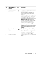
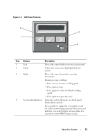
Item Indicator, Button, or Icon Connector 7 LCD panel 8 Optical drive (optional) 9 Tape drive (optional) 10 Front bezel lock Description LCD panel - Provides system ID, status information, and system error messages. Provides system ID, status information, and system error messages. The LCD lights blue during normal system operation. The LCD lights amber when the system needs attention, and the LCD panel displays an error code followed by descriptive text. NOTE: If the system is connected to AC power and an error has been detected, the LCD lights amber regardless of whether the system has been powered on. One or two optional SATA DVD-ROM or DVD+RW drives. NOTE: DVD devices are data only. One optional half-height (using one drive bay) tape drive. Secures the front bezel to the system. LCD Panel Features The system's LCD panel provides system information, status, and error messages to signify when the system is operating correctly or when the system needs attention. See "LCD Status Messages" on page 25 for information about specific status codes. The LCD backlight lights blue during normal operating conditions and lights amber to indicate an error condition. When the system is in standby mode, the LCD backlight is off and can be turned on by pressing the Select button on the LCD panel. The LCD backlight will remain off if LCD messaging is turned off through the BMC or iDRAC utility, the LCD panel, or other tools. 14 About Your System
-
 1
1 -
2
-
3
-
4
-
5
-
6
-
7
-
8
-
 9
9 -
 10
10 -
 11
11 -
 12
12 -
 13
13 -
 14
14 -
 15
15 -
 16
16 -
 17
17 -
 18
18 -
 19
19 -
20
-
21
-
22
-
23
-
24
-
25
-
26
-
27
-
28
-
29
-
30
-
31
-
32
-
33
-
34
-
35
-
36
-
37
-
38
-
39
-
40
-
41
-
42
-
43
-
44
-
45
-
46
-
47
-
48
-
49
-
50
-
51
-
52
-
53
-
54
-
55
-
56
-
57
-
58
-
59
-
60
-
61
-
62
-
63
-
64
-
65
-
66
-
67
-
68
-
69
-
70
-
71
-
72
-
73
-
74
-
75
-
76
-
77
-
78
-
79
-
80
-
81
-
82
-
83
-
84
-
85
-
86
-
87
-
88
-
89
-
90
-
91
-
92
-
93
-
94
-
95
-
96
-
97
-
98
-
99
-
100
-
101
-
102
-
103
-
104
-
105
-
106
-
107
-
108
-
109
-
110
-
111
-
112
-
113
-
114
-
115
-
116
-
117
-
118
-
119
-
120
-
121
-
122
-
123
-
124
-
125
-
126
-
127
-
128
-
129
-
130
-
131
-
132
-
133
-
134
-
135
-
136
-
137
-
138
-
139
-
140
-
141
-
142
-
143
-
144
-
145
-
146
-
147
-
148
-
149
-
150
-
151
-
152
-
153
-
154
-
155
-
156
-
157
-
158
-
159
-
160
-
161
-
162
-
163
-
164
-
165
-
166
-
167
-
168
-
169
-
170
-
171
-
172
-
173
-
174
-
175
-
176
-
177
-
178
-
179
-
180
-
181
-
182
-
183
-
184
-
185
-
186
-
187
-
188
-
189
-
190
-
191
-
192
-
193
-
194
-
195
-
196
-
197
-
198
-
199
-
200
-
201
-
202
-
203
-
204
-
205
-
206
-
207
-
208
-
209
-
210
-
211
-
212
-
213
-
214
 |
 |