Dell PowerEdge T710 Hardware Owner's Manual - Page 87
Cooling Shroud, Removing the Cooling Shroud
 |
View all Dell PowerEdge T710 manuals
Add to My Manuals
Save this manual to your list of manuals |
Page 87 highlights
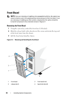
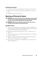
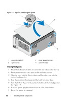
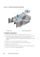
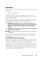
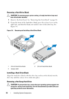
8 Reattach any peripherals and connect the system to an electrical outlet. 9 Turn on the system and attached peripherals. Cooling Shroud The cooling shroud directs airflow over the system processor and memory modules. WARNING: Only trained service technicians are authorized to remove the system cover and access any of the components inside the system. Before you begin this procedure, review the safety instructions that came with the system. WARNING: The memory modules and heat sink can get very hot during normal operation. Ensure that the memory modules and heat sink have had sufficient time to cool before you touch it. CAUTION: Never operate your system with the cooling shroud removed. Overheating of the system can develop quickly, resulting in shutdown of the system and loss of data. Removing the Cooling Shroud 1 Turn off the system and attached peripherals. Disconnect the system from the electrical outlet and periperals. 2 Rotate the system feet inward and lay the system on a flat surface. See Figure 3-4. 3 Open the system. See "Opening the System" on page 85. 4 Push the blue tab towards the direction of the arrow and lift out the cooling shroud. See Figure 3-5. Installing System Components 87
-
 1
1 -
2
-
3
-
4
-
5
-
6
-
7
-
8
-
9
-
10
-
11
-
12
-
13
-
14
-
15
-
16
-
17
-
18
-
19
-
20
-
21
-
22
-
23
-
24
-
25
-
26
-
27
-
28
-
29
-
30
-
31
-
32
-
33
-
34
-
35
-
36
-
37
-
38
-
39
-
40
-
41
-
42
-
43
-
44
-
45
-
46
-
47
-
48
-
49
-
50
-
51
-
52
-
53
-
54
-
55
-
56
-
57
-
58
-
59
-
60
-
61
-
62
-
63
-
64
-
65
-
66
-
67
-
68
-
69
-
70
-
71
-
72
-
73
-
74
-
75
-
76
-
77
-
78
-
79
-
80
-
81
-
 82
82 -
 83
83 -
 84
84 -
 85
85 -
 86
86 -
 87
87 -
 88
88 -
 89
89 -
 90
90 -
 91
91 -
 92
92 -
93
-
94
-
95
-
96
-
97
-
98
-
99
-
100
-
101
-
102
-
103
-
104
-
105
-
106
-
107
-
108
-
109
-
110
-
111
-
112
-
113
-
114
-
115
-
116
-
117
-
118
-
119
-
120
-
121
-
122
-
123
-
124
-
125
-
126
-
127
-
128
-
129
-
130
-
131
-
132
-
133
-
134
-
135
-
136
-
137
-
138
-
139
-
140
-
141
-
142
-
143
-
144
-
145
-
146
-
147
-
148
-
149
-
150
-
151
-
152
-
153
-
154
-
155
-
156
-
157
-
158
-
159
-
160
-
161
-
162
-
163
-
164
-
165
-
166
-
167
-
168
-
169
-
170
-
171
-
172
-
173
-
174
-
175
-
176
-
177
-
178
-
179
-
180
-
181
-
182
-
183
-
184
-
185
-
186
-
187
-
188
-
189
-
190
-
191
-
192
-
193
-
194
-
195
-
196
-
197
-
198
-
199
-
200
-
201
-
202
-
203
-
204
-
205
-
206
-
207
-
208
-
209
-
210
-
211
-
212
-
213
-
214
 |
 |