Dell PowerEdge T710 Hardware Owner's Manual - Page 151
Installing the SAS Backplane, Install the Front Bezel. See Installing the Front Bezel
 |
View all Dell PowerEdge T710 manuals
Add to My Manuals
Save this manual to your list of manuals |
Page 151 highlights
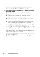
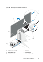
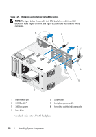
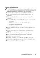
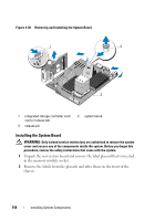
Installing the SAS Backplane WARNING: Only trained service technicians are authorized to remove the system cover and access any of the components inside the system. Before you begin this procedure, review the safety instructions that came with the system. 1 Align the slots on the SAS backplane with the tabs on the chassis. 2 Slide the SAS backplane until the release pin snaps into place. See Figure 3-29. 3 Reconnect the cables that were routed over the notch in the SAS backplane. 4 Reconnect the cables connected to the SAS backplane (see Figure 3-29): • SAS A cable • SAS B cable (available only with 3.5-inch SAS backplane) • hard drive activity indicator cable • backplane power cable 5 Replace all the hard drives. See "Installing a Hot-Swap Hard Drive" on page 91. 6 Replace the cooling shroud. See "Installing the Cooling Shroud" on page 88. 7 Close the system. See "Closing the System" on page 86. 8 Place the system upright and on its feet on a flat, stable surface. 9 Rotate the system feet outward 10 Install the Front Bezel. See "Installing the Front Bezel" on page 85. 11 Reattach any peripherals and connect the system to an electrical outlet. 12 Turn on the system and attached peripherals. Installing System Components 151
-
 1
1 -
2
-
3
-
4
-
5
-
6
-
7
-
8
-
9
-
10
-
11
-
12
-
13
-
14
-
15
-
16
-
17
-
18
-
19
-
20
-
21
-
22
-
23
-
24
-
25
-
26
-
27
-
28
-
29
-
30
-
31
-
32
-
33
-
34
-
35
-
36
-
37
-
38
-
39
-
40
-
41
-
42
-
43
-
44
-
45
-
46
-
47
-
48
-
49
-
50
-
51
-
52
-
53
-
54
-
55
-
56
-
57
-
58
-
59
-
60
-
61
-
62
-
63
-
64
-
65
-
66
-
67
-
68
-
69
-
70
-
71
-
72
-
73
-
74
-
75
-
76
-
77
-
78
-
79
-
80
-
81
-
82
-
83
-
84
-
85
-
86
-
87
-
88
-
89
-
90
-
91
-
92
-
93
-
94
-
95
-
96
-
97
-
98
-
99
-
100
-
101
-
102
-
103
-
104
-
105
-
106
-
107
-
108
-
109
-
110
-
111
-
112
-
113
-
114
-
115
-
116
-
117
-
118
-
119
-
120
-
121
-
122
-
123
-
124
-
125
-
126
-
127
-
128
-
129
-
130
-
131
-
132
-
133
-
134
-
135
-
136
-
137
-
138
-
139
-
140
-
141
-
142
-
143
-
144
-
145
-
 146
146 -
 147
147 -
 148
148 -
 149
149 -
 150
150 -
 151
151 -
 152
152 -
 153
153 -
 154
154 -
 155
155 -
 156
156 -
157
-
158
-
159
-
160
-
161
-
162
-
163
-
164
-
165
-
166
-
167
-
168
-
169
-
170
-
171
-
172
-
173
-
174
-
175
-
176
-
177
-
178
-
179
-
180
-
181
-
182
-
183
-
184
-
185
-
186
-
187
-
188
-
189
-
190
-
191
-
192
-
193
-
194
-
195
-
196
-
197
-
198
-
199
-
200
-
201
-
202
-
203
-
204
-
205
-
206
-
207
-
208
-
209
-
210
-
211
-
212
-
213
-
214
 |
 |