Dell PowerSwitch S4820T Installing the S4820T System
Dell PowerSwitch S4820T Manual
 |
View all Dell PowerSwitch S4820T manuals
Add to My Manuals
Save this manual to your list of manuals |
Dell PowerSwitch S4820T manual content summary:
- Dell PowerSwitch S4820T | Installing the S4820T System - Page 1
Installing the S4820T System April 2014 - Dell PowerSwitch S4820T | Installing the S4820T System - Page 2
use of your computer. CAUTION: A CAUTION indicates either potential damage to hardware or loss of data and tells you how to avoid the problem. WARNING: A WARNING indicates a potential for property damage, personal injury, or death. Copyright © 2014 Dell Inc. All rights reserved. This product is - Dell PowerSwitch S4820T | Installing the S4820T System - Page 3
Contents 1 About this Guide...5 Information Symbols and Warnings...5 Related Documents...6 2 The S4820T Switch 7 Introduction...7 Prerequisites...8 Features...9 Physical Dimensions...9 Chassis Ports...9 Determine System Status...9 LED Displays...10 Orderable S4820T Components... - Dell PowerSwitch S4820T | Installing the S4820T System - Page 4
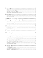
Standards and Compliance Agency Certifications 53 Electromagnetic Compatibility (EMC 54 Product Recycling and Disposal...54 12 Technical Support 57 The iSupport Website...57 Accessing iSupport Services...57 Contacting the Technical Assistance Center 57 Requesting a Hardware Replacement 59 - Dell PowerSwitch S4820T | Installing the S4820T System - Page 5
regarding FTOS versions and system upgrades, contact Dell Networking Technical Support. CAUTION: To avoid electrostatic discharge (ESD) damage, wear guide before you install and power up this equipment. This equipment may contain two power cords. Disconnect both power cords before servicing. - Dell PowerSwitch S4820T | Installing the S4820T System - Page 6
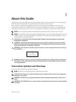
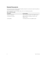
This document provides detailed hardware installation and power-up instructions to get new systems up and running and ready for Documentation Software configuration FTOS Configuration Guide for the S4820T System Command line interface FTOS Command Line Reference Guide for the S4820T System - Dell PowerSwitch S4820T | Installing the S4820T System - Page 7
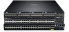
2 The S4820T Switch This chapter contains general features, capabilities, and physical configurations that the S4820T supports. This chapter also contains a list of optional parts available for purchase. Introduction The S4820T system is a top-of-rack (ToR) switch/router product for copper - Dell PowerSwitch S4820T | Installing the S4820T System - Page 8
switch provides converged network support and inter-operates with Dell and third-party ToR devices. The switch supports data center bridging ( (55 meters) over Cat6 UTP copper cable Prerequisites Detailed installation instructions for the S4820T are provided in Site Preparationsand in Install the - Dell PowerSwitch S4820T | Installing the S4820T System - Page 9
memory, P2020/128 MB NOR Flash/2GB DDR III RAM. • Temperature monitoring (TMP75) • Software-readable thermal monitor • Real time clock (RTC) support • Hot-plugging redundant power supply • Current monitoring for Power management • Removable fan that you can manage • Standard 1U chassis high Physical - Dell PowerSwitch S4820T | Installing the S4820T System - Page 10
refer to the FTOS Command Line Reference Guide for the S4820T System and the FTOS Configuration Guide for the S4820T System. LED Displays As shown in the following figures, the S4820T includes LED displays on the front and back of the chassis. - Dell PowerSwitch S4820T | Installing the S4820T System - Page 11
Feature DIAG LED FAN LED STACK LED LOCATOR LED LED Color/Display • Off -- Normal operating • Solid green -- System Booting or Diagnostics Comment PSU side • Solid green -- Fan powered PSU side and running at the expected rpm • Solid red -- Fan failed • Solid blue -- Switch in stacking master - Dell PowerSwitch S4820T | Installing the S4820T System - Page 12
can order the S4820T system in several different configurations. You can also order optional modules and optics separately. You can order the following supported hardware components. • S4820T AC Normal Airflow: 48 port 10G RJ-45 ports with 4 QSFP+ 40G ports, 1 AC power supply and 2 fan subsystems - Dell PowerSwitch S4820T | Installing the S4820T System - Page 13
. Site Selection Install Dell Networking equipment in restricted access areas. A restricted access area is one in which access can only be gained by service personnel by using a special tool, lock, key or other means of security and access is controlled by the authority responsible for the location - Dell PowerSwitch S4820T | Installing the S4820T System - Page 14
Ground the equipment rack to the same ground point the power service in your area uses. The ground path must be permanent. Guide for the S4820T System and FTOS Configuration Guide for the S4820T System. NOTE: Power Supplies and Fan Modules are field replaceable units. Dell Networking does not support - Dell PowerSwitch S4820T | Installing the S4820T System - Page 15
CAUTION: Always disconnect the power cable before you service the power supply slots. CAUTION: Use the power supply cord as the main disconnect device on the AC system. Ensure that the socket-outlet is - Dell PowerSwitch S4820T | Installing the S4820T System - Page 16
16 - Dell PowerSwitch S4820T | Installing the S4820T System - Page 17
is missing or damaged, contact your Dell Networking representative or reseller for instructions. WARNING: Electrostatic discharge (ESD) damage can occur if components are mishandled units (country/region specific) • Getting Started Guide • Safety and Regulatory Information Install the Hardware 17 - Dell PowerSwitch S4820T | Installing the S4820T System - Page 18
• Warranty and Support Information • Software License Agreement 1. Place the container on a clean, flat if components are mishandled. WARNING: This is a condensed reference. Read the safety instructions in your Safety, Environmental, and Regulatory information booklet before you begin. Rack Mounting - Dell PowerSwitch S4820T | Installing the S4820T System - Page 19
of three possible 1U tooled methods (two-post flush mount, two-post center mount, or four-post threaded). Refer to the appropriate instructions for the mounting configuration you're using: Installing ReadyRails - Tool-less Method Installing ReadyRails - Two-Post Flush-Mount Configuration Installing - Dell PowerSwitch S4820T | Installing the S4820T System - Page 20
Installing ReadyRails - Tool-less Method Use this installation method for four-post square hole or unthreaded round hole. 1. With the ReadyRails flange ears facing outward, place one rail between the left and right vertical posts. Align and seat the rear flange rail pegs in the rear vertical post - Dell PowerSwitch S4820T | Installing the S4820T System - Page 21
Installing ReadyRails - Two-Post Flush-Mount Configuration For this configuration, remove the castings from the front of each ReadyRails assembly. Install the Hardware 21 - Dell PowerSwitch S4820T | Installing the S4820T System - Page 22
NOTE: Retain the castings for future rack requirements. It is not necessary to remove the rear flange castings. 1. Remove the castings from the front of each ReadyRails assembly, as shown in item 1 in the following figure. Remove the two screws from each front flange ear (on the switch side of the - Dell PowerSwitch S4820T | Installing the S4820T System - Page 23
Installing ReadyRails - Two-Post Center-Mount Configuration 1. Slide the plunger bracket rearward until it clicks into place and secure the bracket to the front post flange with two user-supplied screws, as shown in item 1 in the following figure. Figure 6. Two-post Center-mount Configuration 2. - Dell PowerSwitch S4820T | Installing the S4820T System - Page 24
NOTE: Retain the castings for future rack requirements. 1. Remove the flange ear castings from each end of the ReadyRails assemblies. Remove the two screws from each flange ear, and remove each casting with a Torx driver, as shown in item 1 in the figure. 2. For each rail, attach the front and rear - Dell PowerSwitch S4820T | Installing the S4820T System - Page 25
Attaching Switch Rails to the Switch and Mounting the Chassis You can mount the switch in 1U front-rack or 1U two-post (flush and center) configurations. Before you mount the chassis, configure the rails and attach them to the switch. Refer to one of the following procedures for the mounting - Dell PowerSwitch S4820T | Installing the S4820T System - Page 26
point. Installing the SFP+ and QSFP+ Optics The S4820T has four quad small form-factor pluggable plus (QSFP+) optical ports. For a list of supported optics, refer to the S4820T data sheet at http://dell.com or contact your Dell Networking representative. CAUTION: ESD damage can occur if the - Dell PowerSwitch S4820T | Installing the S4820T System - Page 27
QSFP+ Ports to SFP+ or RJ-45 Ports The S4820T supports splitting a single 40G QSFP port into four 10G SFP+ ports or four 10G RJ-45 using one of the supported breakout cables. For the system to recognize the port type change, enter the stack - Dell PowerSwitch S4820T | Installing the S4820T System - Page 28
28 - Dell PowerSwitch S4820T | Installing the S4820T System - Page 29
PSU fail, you must replace the entire PSU. For fan tray replacement procedures, refer to Install Fans. Important Points to Remember The S4820T supports two hot-swappable power supplies with integrated fans that provide cooling for the chassis. • The PSU slides into the slot smoothly. Do not force - Dell PowerSwitch S4820T | Installing the S4820T System - Page 30
, use the show logging command. For more information, refer to the System Logs chapters of the FTOS Command Line Reference Guide for the S4820T System and FTOS Configuration Guide for the S4820T System. WARNING: Although the switch can run on one PSU, Dell Networking highly recommends using two PSUs - Dell PowerSwitch S4820T | Installing the S4820T System - Page 31
PSU or the S4820T chassis. NOTE: If a PSU fails, you must completely replace it. There are no field serviceable components in the PSU. To request a hardware replacement, refer to Technical Support. NOTE: If you use a single PSU, you must install a blank plate in the other PSU slot. Dell Networking - Dell PowerSwitch S4820T | Installing the S4820T System - Page 32
Figure 10. DC Power Connector and Wiring Block 1. Screws 2. Wiring Block 3. Power Connector To connect a S4820T DC PSU to the site's DC power source, follow these steps: 1. Strip 1/2" of insulation from each of the power connector's wires (red and black), as shown in the figure. 2. Insert each of - Dell PowerSwitch S4820T | Installing the S4820T System - Page 33
NOTE: To remove the power connector from an S4820T DC PSU, squeeze together the levers on both sides of the connector. Doing so disengages the power connector's clamps. While continuing to squeeze, pull the power connector from the DC PSU socket. Power Supplies 33 - Dell PowerSwitch S4820T | Installing the S4820T System - Page 34
34 - Dell PowerSwitch S4820T | Installing the S4820T System - Page 35
shuts down in one minute. In addition to the integrated fan/power supply modules, you can order and install fan modules separately. The S4820T supports two airflow direction options. Do not mix airflow types in a chassis; you can use only a single airflow direction in a chassis. If the airflow - Dell PowerSwitch S4820T | Installing the S4820T System - Page 36
, use the show logging command. For more information, refer to the System Logs chapters of the FTOS Command Line Reference Guide for the S4820T System and FTOS Configuration Guide for the S4820T System. CAUTION: DO NOT mix airflow directions. Both fans must use the same airflow direction (I/O to - Dell PowerSwitch S4820T | Installing the S4820T System - Page 37
7 Supply Power and Power Up the System Supply power to the S4820T after the chassis is mounted in a rack or cabinet. Dell Networking recommends re-inspecting your system prior to powering up. Verify that: • The equipment is properly secured to the rack. • The equipment rack is properly mounted and - Dell PowerSwitch S4820T | Installing the S4820T System - Page 38
38 - Dell PowerSwitch S4820T | Installing the S4820T System - Page 39
. The lower QSFP+ ports are labeled 48 and 56. The upper QSFP+ ports are labeled 52 and 60. NOTE: Data center bridging (DCB) is not supported if you use ports 0 to 47 for stacking. Important Points to Remember When stacking the S4820T, ensure that: • You configure data ports as stacking ports - Dell PowerSwitch S4820T | Installing the S4820T System - Page 40
a group as data ports. You can connect the systems while they are powered down or up. Stacking ports are bi-directional. The S4820T supports stacking in either a ring or a cascade topology, as shown in the following figure. To provide redundant connectivity, Dell Networking recommends using the ring - Dell PowerSwitch S4820T | Installing the S4820T System - Page 41
of the second cable into stack port 56 on chassis 1 (bottom). Connecting Three S4820T Systems CAUTION: Use only Dell Networking-supported stacking cables to connect S4820T systems. To provide backup connectivity and increased data transfer between the systems, Dell Networking recommends inserting - Dell PowerSwitch S4820T | Installing the S4820T System - Page 42
You can use any of the RJ-45 or QSFP+ ports for stacking, provided you configure ports as stacking ports. To connect three S4820T systems in a ring, as shown in the figure, start with the S4820T at the bottom of the stack and follow these steps: NOTE: The port numbers in the following procedure are - Dell PowerSwitch S4820T | Installing the S4820T System - Page 43
avoid stack management conflicts. For more information about removing a unit from a stack and other stacking commands, refer to the Stacking chapter in the FTOS Configuration Guide for the S4820T System and the Stacking Commands chapter in the FTOS Command Line Reference - Dell PowerSwitch S4820T | Installing the S4820T System - Page 44
44 - Dell PowerSwitch S4820T | Installing the S4820T System - Page 45
9 Console Ports You can access the S4820T directly through the console port at the input/output (I/O) side of the system. Accessing the RJ-45 Console Port (RS-232) The RS-232/RJ-45 console port is labeled on the PSU-side of the S8420T chassis (the I/O side), as shown in the following figure. Figure - Dell PowerSwitch S4820T | Installing the S4820T System - Page 46
Default Configuration A version of FTOS is preloaded onto the S4820T; however, the system is not configured when you power up for the first time (except for the default host name, which is FTOS). You must configure the system using the CLI. 46 Console Ports - Dell PowerSwitch S4820T | Installing the S4820T System - Page 47
is incorrectly replaced. NOTE: Replace the battery only with same or equivalent type. Dispose of the batteries according to the manufacturer's instructions. Table 6. S4820T Chassis Physical Design Parameter Specifications Height 1.71 inches (43.5 mm) Width 17.09 inches (434 mm) Depth 18.11 - Dell PowerSwitch S4820T | Installing the S4820T System - Page 48
Parameter Reliability Specifications MTBF 355,178 hours NOTE: The table below represents the DC PSU's capabilities and does not represent S4820T operation. The power supply operates within all specified limits over the following input voltage range. Table 9. DC Input Specification Parameter Min/ - Dell PowerSwitch S4820T | Installing the S4820T System - Page 49
• Dell Networking (PVST+) • MTU (12,000 bytes) Technical Specifications 49 - Dell PowerSwitch S4820T | Installing the S4820T System - Page 50
50 - Dell PowerSwitch S4820T | Installing the S4820T System - Page 51
environment. This equipment generates, uses, and can radiate radio frequency energy. If it is not installed and used in accordance to the instructions, it may cause harmful interference to radio communications. Operation of this equipment in a residential area is likely to cause harmful interference - Dell PowerSwitch S4820T | Installing the S4820T System - Page 52
Canadian Department of Communication Statement European Union EMC Directive Conformance Statement This product is in conformity with the protection requirements of EU Council Directive 2004/108/EC on the approximation of the laws of the Member States relating to electromagnetic compatibility. Dell - Dell PowerSwitch S4820T | Installing the S4820T System - Page 53
For Interference by Information Technology Equipment (VCCI). If this equipment is used in a domestic environment, radio disturbance may arise. When such trouble occurs, the user may be required to take corrective actions. Korean Certification of Compliance Korean Package Label Safety Standards and - Dell PowerSwitch S4820T | Installing the S4820T System - Page 54
Safety of Laser Products - Part 1: Equipment Classification Requirements and User's Guide • EN 60825-2 Safety of Laser Products - Part 2: Safety of longer needed. Dell Networking offers various product return programs and services in several countries to assist equipment owners in recycling their IT - Dell PowerSwitch S4820T | Installing the S4820T System - Page 55
as required by WEEE. For information on Dell Networking product recycling offerings, see the WEEE Recycling instructions on iSupport at: http://downloads.dell.com/Manuals/all-products/esuprt_electronics/ esuprt_docking_stations/dell-superspeed-usb3-dock-stn_Reference%20Guide_en-us.pdf? c=us&l=en&cs - Dell PowerSwitch S4820T | Installing the S4820T System - Page 56
56 - Dell PowerSwitch S4820T | Installing the S4820T System - Page 57
The URL for iSupport is http://force10networks.com/ CSPortal20/Main/Login.aspx. You must have a userid and password to access iSupport services. 1. On the Dell Networking Support page, click the Account Request link. 2. Fill out the User Account Request form and click Send. You will receive your - Dell PowerSwitch S4820T | Installing the S4820T System - Page 58
experienced the failure (This report is included as a section in the output of the show tech-support [nonpaged] command.) • Console captures showing the error messages • Console captures showing the troubleshooting steps taken • Saved messages to a syslog server, if you use one Log in to iSupport - Dell PowerSwitch S4820T | Installing the S4820T System - Page 59
RMA number from Tech Support by opening a support case. Open a support case by: a. Using the Create Service Request form on the the output of show tech-support command.) - Console captures showing the error messages. - Console captures showing the troubleshooting steps taken. - Saved messages
-
 1
1 -
 2
2 -
 3
3 -
 4
4 -
 5
5 -
 6
6 -
 7
7 -
8
-
9
-
10
-
11
-
12
-
13
-
14
-
15
-
16
-
17
-
18
-
19
-
20
-
21
-
22
-
23
-
24
-
25
-
26
-
27
-
28
-
29
-
30
-
31
-
32
-
33
-
34
-
35
-
36
-
37
-
38
-
39
-
40
-
41
-
42
-
43
-
44
-
45
-
46
-
47
-
48
-
49
-
50
-
51
-
52
-
53
-
54
-
55
-
56
-
57
-
58
-
59
 |
 |

Installing the S4820T System
April 2014