Dell PowerSwitch S4820T Installing the S4820T System - Page 40
Connecting Two S4820T Systems, S4820T systems
 |
View all Dell PowerSwitch S4820T manuals
Add to My Manuals
Save this manual to your list of manuals |
Page 40 highlights
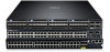
• You place all the ports in a stack-group in stacking mode. NOTE: You cannot use the remaining ports in a group as data ports. You can connect the systems while they are powered down or up. Stacking ports are bi-directional. The S4820T supports stacking in either a ring or a cascade topology, as shown in the following figure. To provide redundant connectivity, Dell Networking recommends using the ring topology when stacking S4820T systems Connecting Two S4820T Systems CAUTION: Use only Dell Networking-supported stacking cables to connect S4820T systems. To provide backup connectivity and increased data transfer between the systems, Dell Networking recommends inserting an additional cable between the two units, in a second stacking port. Refer to the following figure. 40 Connecting the Stacking Ports (Optional)
-
 1
1 -
2
-
3
-
4
-
5
-
6
-
7
-
8
-
9
-
10
-
11
-
12
-
13
-
14
-
15
-
16
-
17
-
18
-
19
-
20
-
21
-
22
-
23
-
24
-
25
-
26
-
27
-
28
-
29
-
30
-
31
-
32
-
33
-
34
-
 35
35 -
 36
36 -
 37
37 -
 38
38 -
 39
39 -
 40
40 -
 41
41 -
 42
42 -
 43
43 -
 44
44 -
 45
45 -
46
-
47
-
48
-
49
-
50
-
51
-
52
-
53
-
54
-
55
-
56
-
57
-
58
-
59
 |
 |
