Dell Studio 1569 Service Manual - Page 31
Replacing the Mini-Cards
 |
View all Dell Studio 1569 manuals
Add to My Manuals
Save this manual to your list of manuals |
Page 31 highlights
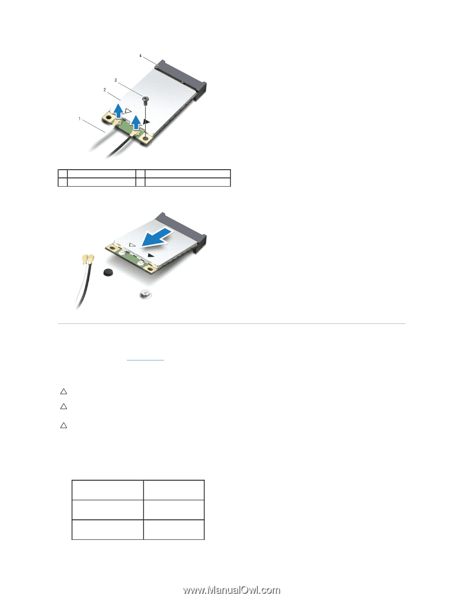
1 antenna cables (2) 3 screw 2 Mini-Card 4 system board connector 7. Lift the Mini-Card out of the system board connector. Replacing the Mini-Card(s) 1. Follow the procedures in Before You Begin. 2. Remove the new Mini-Card from its packaging. CAUTION: Use firm and even pressure to slide the card into place. If you use excessive force, you may damage the connector. CAUTION: The connectors are keyed to ensure correct insertion. If you feel resistance, check the connectors on the card and on the system board, and realign the card. CAUTION: To avoid damage to the Mini-Card, never place cables under the card. 3. With the label on the Mini-Card facing up, insert it at a 45-degree angle into the appropriate system board connector. 4. Press the other end of the Mini-Card down into the slot on the system board and replace the screw that secures the Mini-Card to the system board. 5. Connect the appropriate antenna cables to the Mini-Card. The following table provides the antenna cable color scheme for the Mini-Card(s) supported by your computer. Connectors on the Mini-Card Colors of Antenna Cables main WLAN (white triangle) white auxiliary WLAN (black triangle) black main WWAN (white triangle) white with gray stripe auxiliary WWAN (black triangle) black with gray stripe
-
 1
1 -
2
-
3
-
4
-
5
-
6
-
7
-
8
-
9
-
10
-
11
-
12
-
13
-
14
-
15
-
16
-
17
-
18
-
19
-
20
-
21
-
22
-
23
-
24
-
25
-
 26
26 -
 27
27 -
 28
28 -
 29
29 -
 30
30 -
 31
31 -
 32
32 -
 33
33 -
 34
34 -
 35
35 -
 36
36 -
37
-
38
-
39
-
40
-
41
-
42
-
43
-
44
-
45
-
46
-
47
 |
 |