Dell Studio 1569 Service Manual - Page 43
Replacing the System Board
 |
View all Dell Studio 1569 manuals
Add to My Manuals
Save this manual to your list of manuals |
Page 43 highlights
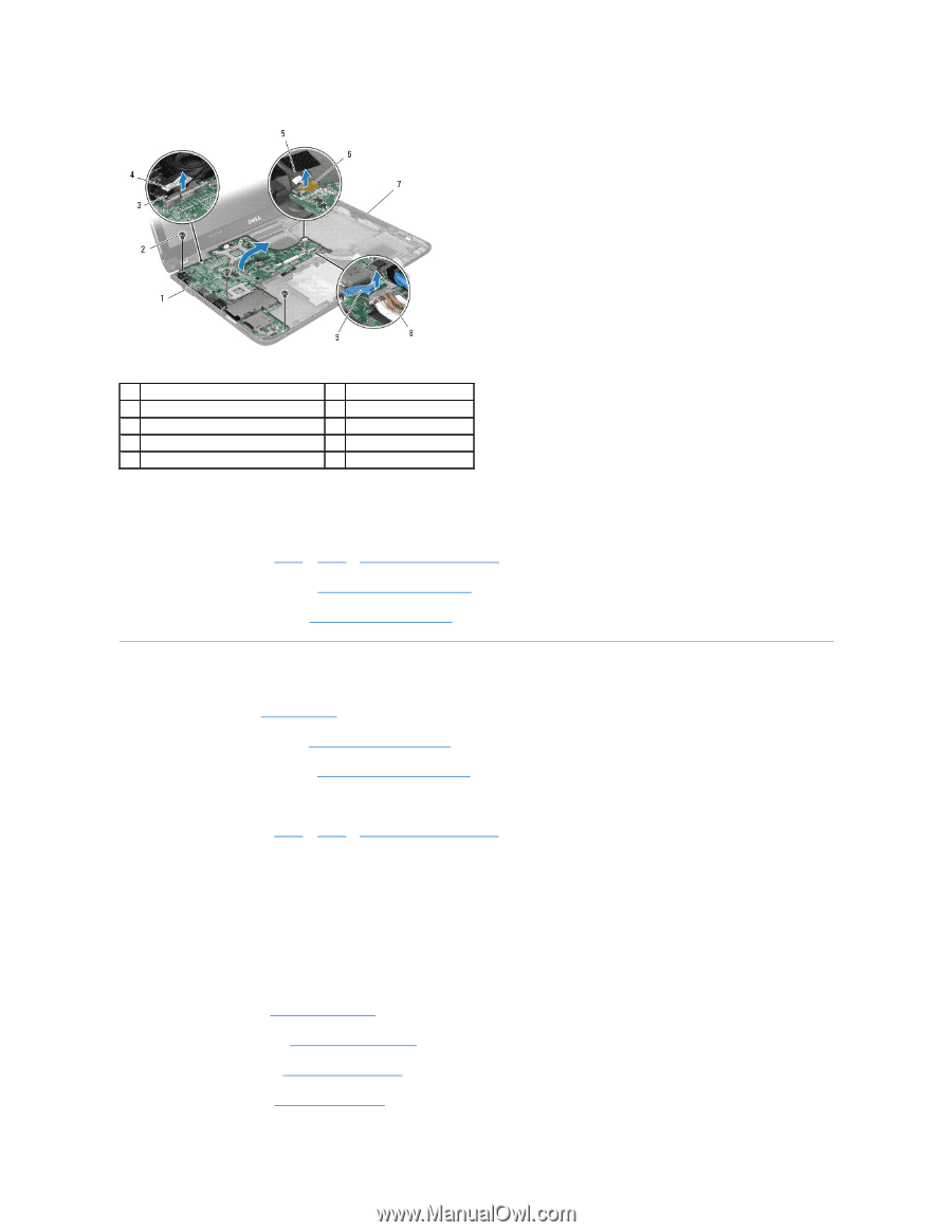
1 system board assembly 3 pull-tab 5 USB cable 7 computer base 9 pull-tab 2 screws (3) 4 display cable 6 pull-tab 8 hard drive cable 16. Carefully ease the connectors on the system board out of the computer base and lift the system board assembly out of the computer base. 17. Turn the system board assembly over. 18. Follow the instructions from step 4 to step 5 in Removing the Coin-Cell Battery. 19. Remove the processor heat sink (see Removing the Processor Heat Sink). 20. Remove the processor module (see Removing the Processor Module). Replacing the System Board 1. Follow the procedures in Before You Begin. 2. Replace the processor module (see Replacing the Processor Module). 3. Replace the processor heat sink (see Replacing the Processor Heat Sink). 4. Ensure that the Mini-Card antenna cables are attached to the computer base. 5. Follow the instructions from step 2 to step 3 in Replacing the Coin-Cell Battery. 6. Connect the hard drive cable and the USB cable to the system board connectors. 7. Turn the system board assembly over and align the connectors on the system board with the slots in the computer base. 8. Connect the display cable to the system board connector. 9. Connect the audio cable to the system board connector. 10. Replace the three screws that secure the system board to the computer base. 11. Replace the speakers (see Replacing the Speakers) and route the USB cable in the routing guides on the right speaker. 12. Replace the processor fan (see Replacing the Processor Fan). 13. Replace the optical drive (see Replacing the Optical Drive). 14. Replace the hard drive (see Replacing the Hard Drive).
-
 1
1 -
2
-
3
-
4
-
5
-
6
-
7
-
8
-
9
-
10
-
11
-
12
-
13
-
14
-
15
-
16
-
17
-
18
-
19
-
20
-
21
-
22
-
23
-
24
-
25
-
26
-
27
-
28
-
29
-
30
-
31
-
32
-
33
-
34
-
35
-
36
-
37
-
 38
38 -
 39
39 -
 40
40 -
 41
41 -
 42
42 -
 43
43 -
 44
44 -
 45
45 -
 46
46 -
 47
47
 |
 |