Dell Z9100 EMC PowerSwitch –ON Installation Guide March 2021 - Page 16
GND lug assembly, NEBS compliance
 |
View all Dell Z9100 manuals
Add to My Manuals
Save this manual to your list of manuals |
Page 16 highlights
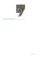
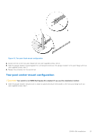
Figure 6. GND lug assembly 1. Remove the two installed M3 screws from the lower-left side of your switch. NOTE: Keep these screws. 2. Remove the bracket assembly from the shipping bag. 3. Clean the bracket and lug surfaces thoroughly, and apply an anti-oxidant solution to the mating surfaces. 4. Attach the switch ground using the Ground cable instructions. 5. Using the two removed screws, attach the GND lug bracket assembly to your switch, as shown. Torque the M3 screws to ±4-5 in-lbs. Figure 7. Attach GND lug assembly 16 NEBS compliance
-
 1
1 -
2
-
3
-
4
-
5
-
6
-
7
-
8
-
9
-
10
-
 11
11 -
 12
12 -
 13
13 -
 14
14 -
 15
15 -
 16
16 -
 17
17 -
 18
18 -
 19
19 -
 20
20 -
 21
21 -
22
-
23
-
24
-
25
-
26
-
27
-
28
-
29
-
30
-
31
-
32
-
33
-
34
-
35
-
36
-
37
-
38
-
39
-
40
-
41
-
42
-
43
-
44
-
45
 |
 |

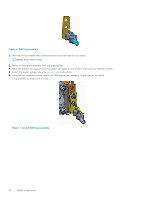
Figure 6. GND lug assembly
1.
Remove the two installed M3 screws from the lower-left side of your switch.
NOTE:
Keep these screws.
2.
Remove the bracket assembly from the shipping bag.
3.
Clean the bracket and lug surfaces thoroughly, and apply an anti-oxidant solution to the mating surfaces.
4.
Attach the switch ground using the
Ground cable
instructions.
5.
Using the two removed screws, attach the GND lug bracket assembly to your switch, as shown.
Torque the M3 screws to ±4–5 in-lbs.
Figure 7. Attach GND lug assembly
16
NEBS compliance