Dell Z9100 EMC PowerSwitch –ON Installation Guide March 2021 - Page 29
AC or DC power supply installation, DC power supply connection
 |
View all Dell Z9100 manuals
Add to My Manuals
Save this manual to your list of manuals |
Page 29 highlights
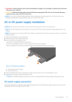
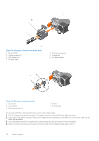
WARNING: Prevent exposure and contact with hazardous voltages. Do not attempt to operate this switch with the safety cover removed. CAUTION: Remove the power cable from the PSU before removing the PSU. Also, do not connect the power cable before you insert the PSU in the switch. NOTE: To comply with the GR-1089 Lightning Criteria for Equipment Interfacing with AC or DC Power Ports, use an external surge protection device (SPD) at the AC or DC input of the router. AC or DC power supply installation NOTE: Do not mix AC and DC PSUs. Only use both AC PSUs or both DC PSUs in the same switch. NOTE: The PSU slides into the slot smoothly. Do not force a PSU into a slot as this action may damage the PSU or the switch. NOTE: Ensure that you correctly install the PSU. When you install the PSU correctly, the power connector is on the right side of the PSU. 1. Remove the PSU blank from the Z9100-ON. 2. Remove the PSU from the electrostatic bag. 3. Insert the PSU into the switch PSU slot. Insert the PSU-exposed PCB edge connector first. The PSU slot is keyed so that you can only fully insert the PSU in one orientation. When you install the PSU correctly, it snaps into place and is flushed with the back of the switch. Figure 17. PSU and fan installation ● Power supply unit on the right ● Fan unit on the left 4. Plug in the appropriate AC three prongs power cable from the switch PSU to the external power source. 5. Repeat steps 1 through 4 using the second PSU slot. NOTE: The Z9100-ON powers up when you connect the cables between the power supply and the power source. DC power supply connection Each DC powered switch comes with a set containing a prewired (3-inch 8 AWG) power supply connector and a four-screw wiring block. One set is provided for each DC PSU. Power supplies 29
-
 1
1 -
2
-
3
-
4
-
5
-
6
-
7
-
8
-
9
-
10
-
11
-
12
-
13
-
14
-
15
-
16
-
17
-
18
-
19
-
20
-
21
-
22
-
23
-
 24
24 -
 25
25 -
 26
26 -
 27
27 -
 28
28 -
 29
29 -
 30
30 -
 31
31 -
 32
32 -
 33
33 -
 34
34 -
35
-
36
-
37
-
38
-
39
-
40
-
41
-
42
-
43
-
44
-
45
 |
 |
