Dell Z9100 EMC PowerSwitch –ON Installation Guide March 2021 - Page 19
Rack or cabinet installation, Rack mount safety considerations
 |
View all Dell Z9100 manuals
Add to My Manuals
Save this manual to your list of manuals |
Page 19 highlights
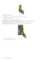
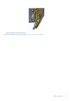
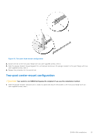
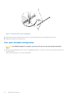
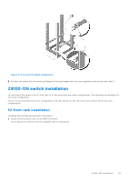
In both configurations, the ground cable is not included. To properly ground the switch, Dell EMC recommends a one- or two-hole lug, M3 or M4 hole size. The switch hole lugs must be a UL-recognized, crimp-type lug. CAUTION: Grounding conductors must be made of copper. Do not use aluminum conductors. NOTE: Coat the one-hole lug with an anti-oxidant compound before crimping. Also, bring any unplated mating surfaces to a bright finish and coat with an anti-oxidant before mating. Plated mating surfaces must be clean and free from contamination. NOTE: The rack installation ears are not suitable for grounding. To connect the ground cable to the switch, follow these steps: 1. Remove the ground cable from the shipping bag and cut it to the desired length. The cable length must facilitate proper operation of the fault interrupt circuits. Use the shortest cable route allowable. 2. Use one of the following to attach the ground cable: ● Using one threaded M3 hole, attached the ground cable to the lug using an M3 screw with a captive internal tooth lock washer, as shown. Torque the screw to ±4-5 in-lbs. ● Using one of the two M4 threaded holes, attach the ground cable to the lug. Use an M4 screw with a captive internal tooth lock washer, as shown. Torque the screw to ±5-6 in-lbs. 3. Attach the other end of the ground cable to a suitable ground point such as the rack or cabinet. The rack installation ears are not a suitable grounding point. Rack or cabinet installation You may either place the switch on a rack shelf or mount the switch directly into a 19" wide, EIA-310- E-compliant rack. Compliant racks include four-post, two-post, or threaded. The ReadyRails system is provided for 1U front-rack and two-post installations. The ReadyRails system includes separately packaged rail assemblies. CAUTION: Your switch is not NEBS Earthquake Z4-compliant if you use the 1U tool-less square-hole or two-post installation methods. WARNING: This guide is a condensed reference. Read the safety instructions in your Safety, Environmental, and Regulatory information booklet before you begin. NOTE: The illustrations in this document are not intended to represent a specific switch. NOTE: Do not the use the mounted ReadyRails as a shelf or a workplace. Rack mount safety considerations ● Rack loading-Overloading or uneven loading of racks may result in shelf or rack failure and can damage the equipment and possible personal injury. Stabilize racks in a permanent location before loading begins. Mount the components starting at the bottom of the rack, then work to the top. Do not exceed your rack's load rating. ● Power considerations-Connect only to the power source specified on the unit. When multiple electrical components are installed in a rack, ensure that the total component power ratings do not exceed the circuit capabilities. Overloaded power sources and extension cables present fire and shock hazards. ● Elevated ambient temperature-If installed in a closed rack assembly, the operating temperature of the rack environment may be greater than the room ambient temperature. Use care not to exceed the 45°C (113°F) maximum ambient temperature of the switch. ● Reduced airflow-Do not compromise the amount of airflow required for safe operation of the equipment. Install the equipment in the rack so that the equipment constantly has the correct amount of airflow surrounding it. ● Reliable earthing-Maintain reliable earthing of rack-mounted equipment. Pay particular attention to the supply connections other than the direct connections to the branch circuit, for example: use of power strips. ● Do not mount the equipment with the back panel facing downward. Z9100-ON installation 19
-
 1
1 -
2
-
3
-
4
-
5
-
6
-
7
-
8
-
9
-
10
-
11
-
12
-
13
-
 14
14 -
 15
15 -
 16
16 -
 17
17 -
 18
18 -
 19
19 -
 20
20 -
 21
21 -
 22
22 -
 23
23 -
 24
24 -
25
-
26
-
27
-
28
-
29
-
30
-
31
-
32
-
33
-
34
-
35
-
36
-
37
-
38
-
39
-
40
-
41
-
42
-
43
-
44
-
45
 |
 |
