Dell Z9100 EMC PowerSwitch –ON Installation Guide March 2021 - Page 33
Fan module installation, Fan module replacement, Fan air filter replacement
 |
View all Dell Z9100 manuals
Add to My Manuals
Save this manual to your list of manuals |
Page 33 highlights
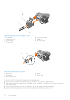
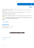
Fan module installation The fan modules are field replaceable. Module slot 1 is on the left side of the switch; module slot 5 is on the right side of the switch. CAUTION: DO NOT mix airflow directions. All reverse or normal fans must use the same airflow direction. If you mix the airflow direction, the switch detects the discrepancy, issues an alarm, and may autoshutdown to avoid heat damage to the components. If an autoshutdown occurs, correct the mixed airflow direction. 1. Take the fan module out of the shipping box. 2. Slide the module into the bay. Figure 21. PSU and fan installation ● PSU is on the right. ● Fan unit is on the left. Fan module replacement 1. Slide the fan module out of the bay. 2. Slide the replacement module into the bay. Fan air filter replacement Environmental factors can decrease the amount of time required between air filter replacements. Check the environmental factors regularly. An increase in temperature and/or particulate matter in the air might affect performance. CAUTION: Check the fan air filters at six-month intervals and replace them as necessary. To accurately determine air filter replacement intervals, regularly monitor the speeds of the cooling fans. An increase in overall fan speed may indicate a clogged filter. You must replace the fan air filters with new filters; you cannot clean and reuse the old fan air filters. Replacement filter media must meet the requirements found in GR-63-CORE. ● Minimum dust arrestance of 65%, per ASHRAE Standard 52.1-1992. OR ● Minimum Efficiency Rating Value (MERV) of 2, per ANSI/ASHRAE Standard 52.2-2007. CAUTION: For Network Equipment Building Systems (NEBS) compliance, use NEBS approved filters. Use fan air filters with reverse blue-banded air flow switches-PSUs and fans. You can replace the air filters individually on each fan within the switch without powering down a PSU module or disrupting traffic. The fan air filter media slides into the frame from the top. No tools are required. 1. Determine which filters to replace. 2. Unlatch and remove the first module that needs the filter replaced. Fans 33
-
 1
1 -
2
-
3
-
4
-
5
-
6
-
7
-
8
-
9
-
10
-
11
-
12
-
13
-
14
-
15
-
16
-
17
-
18
-
19
-
20
-
21
-
22
-
23
-
24
-
25
-
26
-
27
-
 28
28 -
 29
29 -
 30
30 -
 31
31 -
 32
32 -
 33
33 -
 34
34 -
 35
35 -
 36
36 -
 37
37 -
 38
38 -
39
-
40
-
41
-
42
-
43
-
44
-
45
 |
 |
