Dell Z9100 EMC PowerSwitch –ON Installation Guide March 2021 - Page 18
Z9100–ON installation, Unpack, Ground cable
 |
View all Dell Z9100 manuals
Add to My Manuals
Save this manual to your list of manuals |
Page 18 highlights
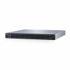
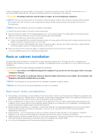
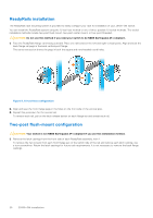
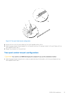
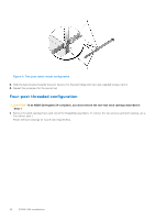
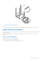
5 Z9100-ON installation To install the Z9100-ON switch, complete the installation procedures in the order described. Always handle the Z9100-ON and its components with care. Avoid dropping the switch or its field replaceable units (FRUs). NOTE: ESD damage can occur if components are mishandled. Always wear an ESD-preventive wrist or heel ground strap when handling the Z9100-ON and its components. As with all electrical devices of this type, take all the necessary safety precautions to prevent injury when installing this switch. NOTE: For more information, see the Open Networking Hardware Diagnostic Guide for the Z9100-ON System. Topics: • Unpack • Ground cable • Rack or cabinet installation • Z9100-ON switch installation • Optics installation • Port connectivity • Switch power up • After Z9100-ON installation • Switch replacement Unpack NOTE: Before unpacking the switch, inspect the container and immediately report any evidence of damage. When unpacking the Z9100-ON switch, ensure that the following items are included: ● One Z9100-ON switch ● One RJ-45 to DB-9 female cable ● Two sets of rail kits, no tools needed ● Two PSUs ● Five fan units ● Two country- and region-specific AC or DC power cables ● Dell Networking Getting Started Guide for the Z9100-Open Networking (ON) System ● Safety and Regulatory Information ● Warranty and Support Information Ground cable NOTE: For AC-powered switches, although the third conductor of the AC power cord provides a ground path, Dell EMC recommends grounding your switch with a dedicated ground wire. NOTE: For DC-powered switches, the only way to safely ground your switch is to attach a dedicated ground wire. Depending on the type of switch, to attach a ground cable to the switch, you need one of the included M3 or M4 screws. The switch ships with one of the following two configurations: ● One threaded hole using an included M3 screw. ● Two threaded holes using one of the two included M4 screws. 18 Z9100-ON installation
-
 1
1 -
2
-
3
-
4
-
5
-
6
-
7
-
8
-
9
-
10
-
11
-
12
-
 13
13 -
 14
14 -
 15
15 -
 16
16 -
 17
17 -
 18
18 -
 19
19 -
 20
20 -
 21
21 -
 22
22 -
 23
23 -
24
-
25
-
26
-
27
-
28
-
29
-
30
-
31
-
32
-
33
-
34
-
35
-
36
-
37
-
38
-
39
-
40
-
41
-
42
-
43
-
44
-
45
 |
 |